• The move to the new server is done. There are some software and database maintenance updates in process. This has us passing the hat around to help out. We appreciate any donations. Seriously, even a dollar helps. The payment page may be found here - https://www.audiokarma.org/support.html

Clip light on, But no FAULT light...

AyEss

Member
hi guys..

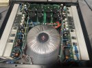
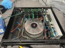
picked up a power amp tonight.. just for cheap.. a C-Mark MR2650.... I have no idea if they are any good, or what...

Seller stated "powers up, But red light on channel B"....

Sure enough, Got it home.... Powers up fine without Dim bulb..
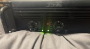
Both Channel relays click, and both channels go to READY green light.... Like they are both ready to receive a signal...
But channel B CLIP light is very dimly illuminated....
and ofc.... No FAULT light appears.....

All appears to be powering up fine.. Minus the CLIP light very dimly lit, On Channel B....

Ideas?!?!
First time ive come across this tbh...
I dont want to connect speakers or pass a signal through it yet, Until i got that CLIP light to go out....

Am i right in thinking, I should be looking at the pre-amp section?!?!
(Im not a professional by any means... I learn as i go, and have fun attempting it)

cheers

(picture attached)
 

Attachments

  • Amp.jpg
    Amp.jpg
    60.6 KB · Views: 21
Register to hide this ad
I would be looking at the clipping indicator circuit.

Unit appears to be a power amp. If so, it has no preamp section.
 
I would be looking at the clipping indicator circuit.

Unit appears to be a power amp. If so, it has no preamp section.
Would that be on the Amp "module"?!?!
Or the front board etc?!?

Thanks
 

Attachments

  • Photo 2023-11-20 07.15.02 pm.jpg
    Photo 2023-11-20 07.15.02 pm.jpg
    158.5 KB · Views: 36
The Amp Modules each side.. Have the common NE5532P 8dip OPAMP.... So im gathering it has a pre-amp section?!?!
 
I would guess those are being used as diff amps...ahead of drivers and outputs. No preamp functions in a power amp.
oh okay :) Learn something new every day :)

So where should i be looking, for the Clip indicator circuitry? On the amp module itself?
Or would that be located on the front PCB, along with the potentiometers and LED's?
As from a quick glance, I notice it has some TO-220 package devices on it, Along with some capacitors, a couple of tuneable pots etc....
So im gathering the front board, does more than just hold the gain potentiometers?!?!?!

Sorry if questions sound dumb... I am not a professional.. I do this for fun... To try and learn :)
Im fairly okay at following schematics, But im just unable to find one...

I was considering swapping the Modules to opposite sites, and see if the Clip light changes sides too... That way it would rule out a problem with the Amp module or not.... If Clip light still remains dimly lit on Channel B side... Then i guess that would show me that the issue is elsewhere?!?!?
 
Awesome bud.. Thankyou....
Further Update though.. I found this amp to be internally identical to the Thomann TA 2400

Now to see if i can source a reliable schematic / service manual for that.. :biggrin:
 
Last edited:
Update:

Well i was going to pass a signal through it.. Just to see whether its simply a clip circuitry fault or not..
So done the preliminary DC check at the terminals, before connecting a speaker....
Channel A has 0.3 mV at the terminals... Channel B has 7.7 VOLTS at the terminals... :p
Guess there is more at fault here, than just a Clip circuitry issue...

Suprising that the relay clicks at all tbh.. and allows it to pass a signal through it, With that amount of DC voltage present...
 
I disconnected one of the wires from the amp module, that goes to the rear speaker terminal board.... and now no longer get the CLIP light illuminate when i power the amp up?!?!
All powers up as should....

EDIT: Scratch that... Powered up fine the first time.. 2nd time, It tripped my house electrics :biggrin: (i like to giveit time to warm up, and try powering the 2nd time, to see if the fault is intermittent) - It only trips my electrics, if i disconnect it from the rear speaker terminal panel....
 

Attachments

  • IMG_1545.JPG
    IMG_1545.JPG
    122.3 KB · Views: 11
Last edited:
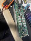
BIG UPDATE: Since both channel boards are identical... a symetrical design.. I swapped the boards sides...
To see if the CLIP light fault will then follow to Channel A.....

NOPE.....

With Channel B board in Channel A side.... and Vice Versa..... The CLIP light still illuminates on Channel B side.... Like originally....
and 7vDC still remains at Channel B speaker terminals.. Even with the working Channel A board connected to that side....

Hmmmm... So it cant be a fault on the Channel amplification boards itself.......

Ideas?!?!
 
Last edited:
Pull and check the outputs.
Transistors on each board?

As i said.. Channel B is the board that shows the clipping light at 7v DC at the terminals.. Channel A is perfect...
But if i put channel A board, over at Channel B side.... and Channel B board at Channel A side... the fault still shows at Channel B CLIP light, and DC at channel B terminals...

Surely if it was the output transistors on Channel B board... The fault would follow over to Channel A CLIP light, when i connected Channel B board into Channel A location?!?!

When Channel B board (originally presumed faulty), is connected at Channel A side.... That channel then functions perfectly....
 
When you move the board, does that mean you are just swapping the whole assy, heat sinks and all to the 1/4” spade connections on the opposite side? Are they 100 % interchangeable, or is there some smaller connections that must stay with each board?
 
When you move the board, does that mean you are just swapping the whole assy, heat sinks and all to the 1/4” spade connections on the opposite side? Are they 100 % interchangeable, or is there some smaller connections that must stay with each board?
im taking the complete board, with heatsinks attached.. and connecting it to the spade terminals of the other side.... Both channel boards are identical... 100% mirror image of eachother.. So im disconnecting model from one side, and connecting it in the other side....

and fault still continued to show the CLIP light, on Channel B...
 
Seems like you’ve pinpointed the problem to the circuitry that doesn’t move then.
Aren’t the speaker outputs on the boards that you moved?
 
Seems like you’ve pinpointed the problem to the circuitry that doesn’t move then.
Aren’t the speaker outputs on the boards that you moved?
no bud... terminal board is at the back...
But front gain potentiometers are on a PCB too, which looks to have a few capacitors on it.. and some "turn" pots... I dont know if thats anything to do with it all, or not...

Im about to check rail voltages, and compare to "channel A side".... But honestly... Im confused of which wires will be what.... After bridge rectification...
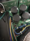
it has 5 wires.... 2 together... then single Red on its own... then 2 more together....

blue and yellow are next to eachother.. then Red on its own........ then green and white wires next to eachother....

I cant find a schematic to help me.. and im very nervous about probing live wires, incase i touch 2 of the wrong ones and blow something / zap myself haha
 

Attachments

  • IMG_1562.JPG
    IMG_1562.JPG
    120.4 KB · Views: 7
Back
Top Bottom