• The move to the new server is done. There are some software and database maintenance updates in process. This has us passing the hat around to help out. We appreciate any donations. Seriously, even a dollar helps. The payment page may be found here - https://www.audiokarma.org/support.html

Clip light on, But no FAULT light...

Don’t you move the power supply wires when you switch each board side to side?
no bud.. each side has its own wires, bridge rectifiers and bank of filter caps etc...
and since the fault is staying on one side.. I want to make sure the power is fine, to that side...

I move them, In terms of.... Touch them.. to disconnect them from the boards.... But i dont move them to the other side... Each side has its own wires...
 
Maybe?!?! An update....

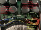
4 bridge rectifiers on the main power supply board.
I believe 2 for each side....

Channel A side - Both Rectifiers show a forward voltage in diode mode....
But on Channel B side.... Only 1 shows correct readings in diode mode....
The far right one.... Which is Channel B one.. is giving me OL on my Multimeter.... (Open Leads)........ (the side im having issues with)...

Would / Could, that be an issue?
Obviously it can be an issue.... If it isnt working.... Its not doing much good hahaha.
But... Can this cause the symptoms im having with this amp?
CLIP light on.. but dimly lit.. On channel B..... and 7v DC at Channel B speaker terminals......

EDIT: Looking at it more closely now... The solder joints do look a little iffy.... Look very dark grey and dry...
Perhaps they have been working too hard.... Probably lower spec'd rated ones, To save a few pennies in manufacturing haha
 

Attachments

  • IMG_1563.JPG
    IMG_1563.JPG
    139.9 KB · Views: 10
Last edited:
With the amp boards removed on both sides, measure the voltages out of the supply on the plugs that would be supplying the boards on each side and compare them.
 
With the amp boards removed on both sides, measure the voltages out of the supply on the plugs that would be supplying the boards on each side and compare them.
There's like 7 wires and spade terminals for each channel.. I have absolutely no idea what ones i should be poking at., haha....

But i removed the Bridge Rectifiers... All testing okay out of circuit... Maybe it was just reading poorly in circuit, Due to all of the main filter caps.....

I thought i'd inspect the rear speaker terminal board... Honestly, Just the speakon and 1/4 jack sockets.. And some ceramic disc things haha... I have no idea what they are... But they are sorta like, what you'd expect to see on an In-rush limiter circuit.... Those Brown/Black cermic discs with 2 legs....

Only thing i can think of now.. Is the front PCB, that holds the Gain Potentiometers...
That has a few Capacitors on it.. and from what i can slightly see... 3 or 4 TO-220 devices..
 
You probably realize you’re not really going at this in a slow systematic fashion…
Measure each one of those 7 wires on each channel, ac and dc. Write them down compare them to each other.
The random shotgun approach seldom works.
 
You probably realize you’re not really going at this in a slow systematic fashion…
Measure each one of those 7 wires on each channel, ac and dc. Write them down compare them to each other.
The random shotgun approach seldom works.
I know haha...
I am ridiculously nervous about going near electrics while powered up..
I got a zap from a main filter cap, about 3 years ago.. Which put me on a temp pace-maker to try and get my heart back in rythme, otherwise surgery was required, To stop my heart and restart it again.... I am all find now.. But as you can imagine, The nerves haha...
I love the aspect of trying to fault find, Soldering etc.. But when it comes to powering things and being near it.... Its a no go from me. lol

Well i have just 100% ruled out the front board being the issue...
I didnt realise, I have a AudioHead amplifier in my cupboard, that is fairly similar internally.. well, the Front PCB board is a direct fit anyway.....
Fault still persists, With different front PCB in place....
Atleast thats 1 thing i can defo rule out.. haha
 
With the amp boards removed on both sides, measure the voltages out of the supply on the plugs that would be supplying the boards on each side and compare them.
well i thought i'd brave it.. .Disconnected and removed both Amplifier boards, to gain access to wiring, To check voltages on power board...

Everything removed, Flicked the power switch... Lights in my room still dimmed, Even with no amp boards connected to suck power?!?!?!?!

and it tripped my electric breaker....... Im not 100% sure, if it was just my eyes playing tricks on me, Or light refracting on my glasses lense.. But im pretty sure when i flicked the power switch, There was a quick blue-ish flash on the Bridge Rectifier pins?!?!?!

So 100% either power board, or the rear speaker terminal board.... As the speaker terminal board also contains In-rush current circuitry....4 of those ceramic disc's, a relay and a big green capacitor.....
 
Last edited:
Now you’re getting somewhere!
Next, disconnect the transformer from the power board and repeat the test.
This will tell you if you have a damaged transformer or bad power supply.
You really should make a dim bulb tester though to prevent tripping the breaker and protect the unit from further damage.
 
Now you’re getting somewhere!
Next, disconnect the transformer from the power board and repeat the test.
This will tell you if you have a damaged transformer or bad power supply.
You really should make a dim bulb tester though to prevent tripping the breaker and protect the unit from further damage.

Disconnect it from just the power board? IE: the board that only has bridge rectifiers and the main filter caps on it...
As some transformer wires go to the back board, for the In-rush current circuit...

Good call! I will connect it via Dim Bulb from now on....
 
Now you’re getting somewhere!
Next, disconnect the transformer from the power board and repeat the test.
This will tell you if you have a damaged transformer or bad power supply.
You really should make a dim bulb tester though to prevent tripping the breaker and protect the unit from further damage.
okay.. So a little explaination of how the circuit goes....

Transformer wires go into the "power board".... Which consists of 4x Bridge rectifiers, and bank of Main filter caps....
Then a few transformer wires go directly to the back PCB board, Where the speaker terminals and In-rush current circuitry is...

I disconnected all the wires that go from the transformer, To the "power board" (rectifiers and filter caps board), But left the wires connected from transformer to back PCB.. As the power switch is connected on the back PCB too...

Powered it up... No lights in my house dimmed, No breakers tripped, No funny noises etc... Just a nice gentle hum from the transformer, As you'd expect.....

So...... Being as the Transformer is connected to the back PCB in-rush current circuitry, It tells me that the in-rush circuit is fine?!?!
So..... Power board is at fault?!?!
As it only dims my lights and occasionally trips my breaker, when thats connected to the transformer...

On a side note: I did think i was getting a strange reading, last night, When i checked the Bridge Rectifiers with a muiltimeter.... Plus... When looked at closely.. the solder points for the rectifiers, are dull, grey and look iffy......

So maybe i wasnt seeing things earlier.. maybe there actually was a blue spark from the rectifier pins?!?!?!

 
okay.. So a little explaination of how the circuit goes....

Transformer wires go into the "power board".... Which consists of 4x Bridge rectifiers, and bank of Main filter caps....
Then a few transformer wires go directly to the back PCB board, Where the speaker terminals and In-rush current circuitry is...

I disconnected all the wires that go from the transformer, To the "power board" (rectifiers and filter caps board), But left the wires connected from transformer to back PCB.. As the power switch is connected on the back PCB too...

Powered it up... No lights in my house dimmed, No breakers tripped, No funny noises etc... Just a nice gentle hum from the transformer, As you'd expect.....

So...... Being as the Transformer is connected to the back PCB in-rush current circuitry, It tells me that the in-rush circuit is fine?!?!
So..... Power board is at fault?!?!
As it only dims my lights and occasionally trips my breaker, when thats connected to the transformer...

On a side note: I did think i was getting a strange reading, last night, When i checked the Bridge Rectifiers with a muiltimeter.... Plus... When looked at closely.. the solder points for the rectifiers, are dull, grey and look iffy......

So maybe i wasnt seeing things earlier.. maybe there actually was a blue spark from the rectifier pins?!?!?!
So now it seems like it’s the power supply board. Typically a power supply issue affects both channels though.
Does this one have separate power supply circuits? If so you can compare the two of them.
 
So now it seems like it’s the power supply board. Typically a power supply issue affects both channels though.
Does this one have separate power supply circuits? If so you can compare the two of them.
Yes bud.
The power supply board has its seperate sides, for each amp module…
4 caps and 2 bridge Rex’s for each side.
 

Attachments

  • IMG_1564.jpeg
    IMG_1564.jpeg
    152.2 KB · Views: 5
Yes bud.
The power supply board has its seperate sides, for each amp module…
4 caps and 2 bridge Rex’s for each side.
Well you suspect B is bad. Pull all the connections to B, leave A connected and give it a try. If it passes you know the issue is only on the B side.
 
Well you suspect B is bad. Pull all the connections to B, leave A connected and give it a try. If it passes you know the issue is only on the B side.
Already done this bud.
When all connected up normally.
Channel A is perfect.
No clip or fault light on, 0.3vDC at terminals, and passes a signal fine, with a clean output at 8 ohm on oscilloscope….

Channel B is always the side that shows constant CLIP light, and 7.7vDC at terminals, regardless what amp board I connect on B side….
 
Well you suspect B is bad. Pull all the connections to B, leave A connected and give it a try. If it passes you know the issue is only on the B side.
Pulled everything out the case, As i wanted to health check all the components, and give it a dusting, While im at it...
Removed the power board, But the Rectifiers dont have any stamping or rating on them :(
I have no idea what part to replace it with :oops:
 
Post a picture of them here and someone will likely identify them.
How many watts output is the amp rated for?
 
Post a picture of them here and someone will likely identify them.
How many watts output is the amp rated for?

According to the website, Its rated for:
2x 1200w into 4 ohm
2x 760w into 8 ohm....

Ive been looking up about the amplifier, and ive seen a few pages, of people mentioning the bridge rectifiers burning out on this amp...
So possibly get a higher power capable rectifier?!?! So that it runs cooler.....
If thats a possibility..
 
Well.... In a way.. A little annoying....
I removed the bridge rectifiers to test out of circuit.....
Soldered them back in.. and now the amp works perfectly :biggrin:
No CLIP light.. No more crazy vDC at speaker terminals....
Channel A & B now passes a signal perfectly.....
Output waveforms on oscilloscope look perfect..
1khz sine wave test, hooked upto my 4ohm 1000w dummy load resistor..... Kinda made the resistor cry for its life. :yikes:
Amp puts out Waaaaaay more, into 4 ohm.. than i can possibly test... I havent got a dummy load resistor powerful enough haha....

So...... Bad solder joint in the end :biggrin::beerchug:

Thankyou for you're help and input
 
Back
Top Bottom