• The move to the new server is done. There are some software and database maintenance updates in process. This has us passing the hat around to help out. We appreciate any donations. Seriously, even a dollar helps. The payment page may be found here - https://www.audiokarma.org/support.html

Console tube amp help

I am always very careful about any power lines with AC near the signal path and B+ DC (so your wall voltage and likely your heaters here). Things that always scare me are power switches and lights that have AC strafing the whole chassis (as you have) as it gives lots of opportunity for the AC lines to cross key DC lines. I have seen poorly routed AC cause hum in 2-3 amps in the past. You can test this by poking around with something not conductive (don't electrocute yourself! Dangerous voltages in your tube amps!), move some of those AC wires around a bit and see if the hum changes.

But in actuality, hum is always maddening and could come from everything everyone is saying 1) grounding scheme, 2) poor ps supply ripple filtering (by design), 3) loose solder joint somewhere in PS. I usually start with cleaning up wire pathing and making a really nice grounding scheme. You can model the PS and see how much ripple you should expect. I also typically examine every key solder joint to make sure it's real nice and solid.
i guess you could be right on here , it sounds like a back ground Ac 60 cycle hum , i could get rid of run light and switch and try it , maybe i could alter the ground scheme , not sure how to model the power supply
 
have to draw out what it is. Typically it'll be output from the rectifier to a cap, to something, to a cap, to probably a resistor, to another cap, maybe more stages beyond that. The "something" could be either a resistor or a choke. Choke is better, resistor is cheaper. All depends how much money they were looking to spend.

Another question I'd have is what did they do to ground the heater circuit. There are a couple ways to get there, but a grounded center tap or a virtual center tap tends to be the most effective. If there is no CT on the 6v winding, you fake it with a pair of resistors in the 100-470 ohm range. Run one from each leg of the heater circuit to ground. This may be done already, I don't know. Only need one for each 6v circuit, if there is only one running all the tubes, then you need one. Not one per-tube.
 
Thanks every one , im just tired of this amp issue and not even sure where the heater circuit is , there are two power transformer wires that go direct to ground , im not going to draw out a scematic , can i up the uf rate of a cap in power supply ?, if its not a easy fix for me then i may just sell this amp --------can i add a choke to maybe help ? ---as soon as i get time ill try getting rid of on/off switch and pilot lamp and check rout of some wires and check solder connects and maybe add or change a ground wire or two , this is going to be the best i can do for now , ill report back at the test results after. you guys and AK has been great and ill be back with new post about a maggie 9304-10 with a odd input level issue that requires a buffer amp to work at rite level
 
Someone else can help with the choke question but yes, you can always up but never lower, the uf rating and even the voltage of capacitors. As an unwritten rule it's best to stay within 20% if you can.
 
Last edited:
If you want to try to improve he heater wire situation, you can try to replace the heater wires with twisted pairs. The tubes most sensitive to hum will be the small signal tubes. Maybe start by replacing the heater wiring to those first and see if there's any difference.

The heater wiring is probably in series (one tube than the next), and the last tubes in the chain should be the small signal tubes.

You can look up the data sheet for each tube, and see that there are (at least) two pins on each for heater wiring. You can then trace the wires from the PT to the first tube, and the next, etc.
 
maybe see if someone with some experience in playing with mystery equipment can take a look at it and help you figure out what it is, even if nobody knows what it started as. Playing with undocumented gear when you don't have a decent bit of experience is pretty difficult honestly.
 
If you want to try to improve he heater wire situation, you can try to replace the heater wires with twisted pairs. The tubes most sensitive to hum will be the small signal tubes. Maybe start by replacing the heater wiring to those first and see if there's any difference.

The heater wiring is probably in series (one tube than the next), and the last tubes in the chain should be the small signal tubes.

You can look up the data sheet for each tube, and see that there are (at least) two pins on each for heater wiring. You can then trace the wires from the PT to the first tube, and the next, etc.
And i should replace them with a twisted pair ? should the twisted pair be one positive and one negative or just twisted pair of the same positive wire , yes i think i can find the heater wires and replace if thats what it takes
 
i guess you could be right on here , it sounds like a back ground Ac 60 cycle hum , i could get rid of run light and switch and try it , maybe i could alter the ground scheme , not sure how to model the power supply
How does a toggle switch and a run lite
i guess you could be right on here , it sounds like a back ground Ac 60 cycle hum , i could get rid of run light and switch and try it , maybe i could alter the ground scheme , not sure how to model the power supply
but really how does a run light and toggle switch cause hum , you say it leaks ac onto chasis ? --- why does this not happen on my other tube amps ?
 
The heater will be a winding from the transformer. It will have two wires, or three. If there are three, one is a "center tap" and will likely be grounded, so then you will again only have two wires to worry about. These two wires should be twisted, and go from one tube to the next to provide the low voltage heater current each tube needs for operation.
 
The heater will be a winding from the transformer. It will have two wires, or three. If there are three, one is a "center tap" and will likely be grounded, so then you will again only have two wires to worry about. These two wires should be twisted, and go from one tube to the next to provide the low voltage heater current each tube needs for operation.
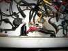
I see the heater circuit , its just one wire that comes out of the power transformer and goes to one out put tube socket term , from there a jumper wire goes to all the rest of tube sockets , out puts and driver tubes , now there is all so a jumper heater wire that goes to the un used pre amp power socket , but this jumper is all so used to power the run pilot lamp , which others have said could be causing my hum issue , so think im going to eliminate that jumper run and pilot light---yes other wires come out of the power transformer and go direct to ground and im sure one of those is the heater center tap ground
 
For now i have gotten rid of on / off switch and that heater jumper wire than ran over to pre amp power socket and the pilot lamp is all so now out of circuit . trying to decide if there may be moor i can do before test out , i take brake from it now ---Please see my magnavox 9304 tube amp post ( when you have time no hurry ) i need advice on that amp too . thank you squid you got me to try something ?
 

Attachments

  • 100_4765.JPG
    100_4765.JPG
    127.6 KB · Views: 20
  • 100_4766.JPG
    100_4766.JPG
    135.8 KB · Views: 20
How does a toggle switch and a run lite

but really how does a run light and toggle switch cause hum , you say it leaks ac onto chasis ? --- why does this not happen on my other tube amps ?
This one looks to be a neon type. Just two rods inside that glow. Sometimes these cause unwanted noise as hum. If it is in fact a filament bulb, don't worry about it. Most other amps use incandesent (filament) bulbs.

I see this on this particular amplifier, the heater wires (6.3volt) are green wires and yes, one of them is grounded so 1/2 heater wire on every tube will be grounded to the chassis.

Normally, two green wires will run to one tube and then from there, two wires to every other tube.

Look up tube data sheets and see which pins are the heater wires. The 6BG6 looks to be pins 1 & 7.

What are the two smaller preamp tubes? 12AX7's? Just for grins, remove both and observe if there is still hum.

Maybe previous owner had problem with hum and tried to eliminate it by changing out the 6L6 to to the 6BG6. :dunno:
 
Last edited:
This one looks to be a neon type. Just two rods inside that glow. Sometimes these cause unwanted noise as hum. If it is in fact a filament bulb, don't worry about it. Most other amps use incandesent (filament) bulbs.

I see this on this particular amplifier, the heater wires (6.3volt) are green wires and yes, one of them is grounded so 1/2 heater wire on every tube will be grounded to the chassis.

Normally, two green wires will run to one tube and then from there, two wires to every other tube.

Look up tube data sheets and see which pins are the heater wires. The 6BG6 looks to be pins 1 & 7.

What are the two smaller preamp tubes? 12AX7's? Just for grins, remove both and observe if there is still hum.

Maybe previous owner had problem with hum and tried to eliminate it by changing out the 6L6 to to the 6BG6. :dunno:
guess it could be a neon type , it was there , i all ways use filament or L E D -- yes i do see the green now , that is for sure the 6.3 volt heater circuit , and ive now taken run light out of circuit and on / off toggle too---- guess im going to set it up for a test soon , -- there not 12ax7s , they are 6AN8A-- just checked the run light with my ohm meter , it reads close to 20 ohm -------------im sure that the hum has been there a long time , previous owner only told me that the 6bg6 tubes where cheaper and easy to find and sounder the same as 6l6 , my on line research does seem to confirm that they are a match to the 6L6
 
OK, I skimmed through the thread, first thing I noticed is that the OPT's are oriented the same way as the PST. That will induce a hum. Try turning both OPT's 90 deg. It's where I would go based on what I've read and seen.
 
OK, I skimmed through the thread, first thing I noticed is that the OPT's are oriented the same way as the PST. That will induce a hum. Try turning both OPT's 90 deg. It's where I would go based on what I've read and seen.
Well they where never turned that way from the factory , yes there is holes to turn them , but i can see these holes where never used , and i fear that turning them will put vulnerable side of out put transformers to close to a very hot running 5u4 rectify tube ! , but i still like your input ! ---------------i have a two channel four way rig here two , pre amp is dynco pass 3x , cross over is sony td-888
 
It looks like all the heater return currents run in the chassis. I see the second green wire connected to a grounded terminal near the back. The power supply common points are grounded at different places and the input jacks look to be chassis grounded but also have a ground wirek running to the ground of the first tube. I don't think you will ever get this amp quiet without some careful rewiring. I would start with the heater wires and run twisted pairs from the green transformer wires to each socket and get the return currents out of the chassis. You will still need a ground reference somewhere. You can leave the one green wire grounded or better yet create a pseudo center tap with a couple of 100ish ohm resistors. The transformer orientation is probably a secondary issue compared to the ground wiring situation.
John
 
Back
Top Bottom