• The move to the new server is done. There are some software and database maintenance updates in process. This has us passing the hat around to help out. We appreciate any donations. Seriously, even a dollar helps. The payment page may be found here - https://www.audiokarma.org/support.html

Convert Dual 505-3 230v for North America

Montycat

Moderator
Staff member
Moderator
Subscriber
There's a 505-3 near me at a decent price but it's a 230v 50hz model. I know the pulleys can be changed to take care of the 50 to 60hz but I still have to find one of course. It uses, as far as I know, the split expanding style but that was on a bunch of tables of that era.

The Service Manual for the 505-3 isn't on Vinylengine though some of the similar models are there. Others use the wiring box that allows for re-routing power to the motor to change from 230 to 115. Can anyone confirm that the 3 version also has this? I'm 95.42% sure it does.
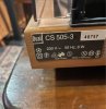
Screenshot_20220908_070529.jpg

Screenshot_20220908_100903.jpg
 
Last edited:
Register to hide this ad
Hi Andrew. According to this 505-3 resource from dual-reference, it appears that it does.

EDIT: Sincerest condolences on the passing of her majesty queen Elizabeth II. May she rest in peace.

Thanks Tom, though I am not sure that confirms it. It certainly says it was an option.

Yes, and thanks to the condolences too. Whatever you think of the monarchy she was a class act.
 
(...) Can anyone confirm that the 3 version also has this? I'm 95.42% sure it does.

No worries, Andrew: The 506-1 and all 505 variants sport just the same little PCB (with the drop-down resistor (for ca. 230 V use), the anti-sparking cap, the main switch (plus inductor L1 in series) and the two phase-shifting caps for the second motor winding). So the 505-3 doesn't differ in terms of 115 V conversion. Oh, and in case you'd wonder about the stobe light branch in the motor wiring scheme, that's a remainder of the combined service manual for the 506-1 and 505, that Dual simply forgot to remove in the service manuals for the 505-1 and 505-2.

Well, and regarding the 60 Hz pulley for the SM100, SM100-1 and SM112, Dualfred still offers that as new old stock replacement part - see there: https://www.dualfred.de/Drive/Pulley--Idler-Wheel--Belt/Antrieb-261939-en.html

Greetings from Munich!

Manfred / lini
 
Thanks Manfred! I hadn't thought to check Dualfred. And yes, the strobe part of the circuit has me wondering.

It's not certain that I will acquire the 505-3 yet. I was offered a 510 today quite cheaply. I will grab it hoping that the motor is the SM-860. If not I can always rob it for the pulley.
 
(...) I was offered a 510 today quite cheaply. (...)

Not a bad model, either.

(...) If not I can always rob it for the pulley.

Not sure, whether I interpret this correctly - but given, that the 60 Hz pulleys for the SM840 & SM860 and for the SM100(-1) & SM112 have different part numbers and the former are 8-pole and the latter 16-pole motors, I'd deem it not all too likely, that a 60 Hz pulley for the former would also work for the latter. But maybe you rather meant, that you could snag the pulley from the SM840 and use it on an SM860 instead.

Greetings from Munich!

Manfred / lini
 
I did see the different part #s for the pulleys so wasn't counting on it working on the different motors.

As an aside, there is an ebay listing for a bunch of Dual pulleys. Trouble is you can't tell what model they are so could be all 50hz or the wrong model.
 
So I got it and opened it up. I could be wrong but I think it has already been reconfigured (electrically at least) for 115v.

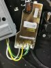
The pins in the picture are numbered 1 to 5 from left to right. Nothing now goes to 1 and 3 wires go to 4. My German is not great but Ge should be short for yellow (gelb), Gn for green and Ws for white. However the motor will not spin with it plugged in.

The guy said it ran "sometimes" but also that he used a step up transformer, assuming it was still a 230v device. He said he did not know much about it though.

Possibly the wires are correct though I will look more carefully before changing anything. Maybe the caps are shot? I have what I think might be correct values for them, or at least the little X2 safety cap. If this has been modded to run at 115v I might have lucked out and the pulley could also be correct.

IMG_20220912_180003.jpg
 
Last edited:
It sure looks wired for 115V. If he ran it w/o the drop resistor with 230V, he may have burnt the motor winding, so make sure it's not open.

You might have something there. I pulled the yellow and white wires from the pins and checked continuity to pin 4 and only get a circuit on one side.
 
Andrew: Regarding the caps, ideally the two phase-shifting caps should also be X2 types, due to these never being completely off (as there'll still be a little current through the anti-sparking cap, when the main switch is off).

Well, and then I'd suggest to check the micro switch itself and the mechanics, that should operate it, 'cause not rarely that gets stuck on the 505ers.

Greetings from Munich!

Manfred / lini
 
(...) I pulled the yellow and white wires from the pins and checked continuity to pin 4 and only get a circuit on one side.

Oh... Not good. And too bad, that Pollin(.de) doesn't offer the SM100 for not much money anymore (they used to sell it for just 10 Euro). Otherwise you could have grabbed one of these and used it with the top plate of the existing SM100-1 instead ('cause that's the only difference between these two variants). Dualfred should still offer the SM100-1, though.

Greetings from Munich!

Manfred / lini
 
. I pulled the yellow and white wires from the pins and checked continuity to pin 4 and only get a circuit on one side.
Yeah, it sounds bad but maybe the switch or caps on the PS board are throwing you off. It appears as yellow/green are one side of the motor and black/white is another. Ohm these with the motor disconnected from the board. See what you're getting. Crossing fingers for that little motor...

EDIT: If it's fried you've got nothing to lose. You can get pretty deep inside these motors and if you're real lucky, you'd spot the split in the winding somewhere like near a terminal, where it's easy to access and solder back together. It's a long shot, but it can keep hope up.
 
Last edited:
(...) but maybe the switch or caps on the PS board are throwing you off.

Don't think so, if Andrew has tested as described. However, I'd also suggest to rather measure the resistance than to just test for continuity. Foremost because the resistance threshold for continuity typically is comparatively low - but also because that threshold may differ quite a bit between different DMM models. And then maybe I'm not the only idiot, who has too many different DMMs to properly remember the specs. Hence I've just looked up two of mine: Continuitiy threshold for the PeakTech 2005 is 90 Ohm - whereas for the McVoice M-501 (alias Mastech MS8209) it's 40 Ohm for the buzzer and 400 Ohm for the display (to show an "OL").

Greetings from Munich!

Manfred / lini
 
I'll get back at it soon! Too much life getting in the way...

In fact I might change meters too. I was working in the garage on this and the meter out there wasn't even a DMM, it was an old Radio Shack analog model. It doesn't have a buzzer, just a meter.
 
The motor is vibrating and trying to spin with power applied. I changed one of the caps, the only one I had in a matching value. No change really though it did spin once.

Off to the electronics store!
 
Damn. Replaced all 3 caps with same values and it's still the same. With coaxing it will sometimes spin. It's not like it's seized either.

I did not replace the resistors. The 5k one I measured in place and it was bang on.
 
I think the 5K (if it's between pins 1 and 4) is the voltage drop resistor in 230V configuration. It's by-passed with the 115V wiring. You really need to establish the integrity of both motor windings.
 
I think the 5K (if it's between pins 1 and 4) is the voltage drop resistor in 230V configuration. It's by-passed with the 115V wiring. You really need to establish the integrity of both motor windings.

Burnt indeed! That's the white/black side which also measures open. I guess I will be looking for a motor. :(

IMG_20220914_150826.jpg
 
Back
Top Bottom