• The move to the new server is done. There are some software and database maintenance updates in process. This has us passing the hat around to help out. We appreciate any donations. Seriously, even a dollar helps. The payment page may be found here - https://www.audiokarma.org/support.html

Correct Output transistor replacements for Sansui 7070

toymanmsp

Active Member
Greetings,

I'm looking to confirm that I have the complementary pairs correct for new output transistors for my 7070. I know that the replacements are the MJ21193G & MJ21194G. I need to confirm that the original 2SA746 replacement is MJ21193G and that the original 2SC1115 replacement is MJ21194G. Thanks.
 
Register to hide this ad
All 2SA transistors are PNP and all 2SC transistors are NPN. The MJ21193G is PNP and the 94 is NPN. Your match up is correct.

- Pete
Thanks, Pete for the quick reply. I found one bad transistor but decided to replace all 4. I was able to get them installed last night. My 7070 still isn't working correctly, as I'm having issues with the driver board. The unit starts (really happy that the new output transistors didn't flake out on me) without the driver board (relay click without it, no click with driver board installed). Skywatcher has been helping me with triaging my 7070. I've looked over the board and have found a few things that should be cleaned up (checking the solders, solder bridges, traces, continuity, etc.) Hopefully, the issue is with the driver board and once I've gone thru the board again, I'll have a working unit. Which would be great so I could finish the additional boards, new relay, and filter caps and get it back into rotation. I miss it. Anyway, thanks again for the quick reply. Really appreciated.
 
Greetings,

I'm looking to confirm that I have the complementary pairs correct for new output transistors for my 7070. I know that the replacements are the MJ21193G & MJ21194G. I need to confirm that the original 2SA746 replacement is MJ21193G and that the original 2SC1115 replacement is MJ21194G. Thanks.
Yep, as @LBPete says, they will work great. You gotta check everything on the driver board right down to the small signal diodes. And while on a DBT, check the DC Offset before the relay. It may simply be too high and the relay won't click in until it's adjusted to less than a half a volt. I haven't heard from you in a while so I don't know where you are at with things. If worse comes to worse you can send me the board. Or ask Pete nicely. :D I own a 7070 with the MJ outputs so I can fully test the board, and adjust it "close" to where you could do the final adjustments.
 
Hi Skywatcher,

Yes, sorry that you haven't heard from me, things have been a bit hectic. I'm studying for my real estate license and haven't had the time to invest. I also knew that the rework of the board would require a significant time investment, which I was able to do last night up until 1:30 am. I think that I've made some good progress. I've gone thru almost the entire board checking continuity on the traces of the driver board, very time-consuming. That said, by doing this I was able to find where I did have several solder bridges, poor solders (either too much or too little), candidly a bit of a mess. I've changed tips on my iron and that appears to have made a difference, the board looks much better. I also found that several of the pads have lifted. I've been able to repair and get continuity on those traces. I'm expecting when I check the board again today, that I'll find a trace or two without continuity. I concluded the evening by turning the unit on without the driver board installed, the relay clicks, good start. I installed the driver board and turned the receiver on (with the dbt) and the dbt did light up, but then died down a fair amount. It wasn't as bright as it had been previously, still no relay click. Even without the relay clicking, I'll take that as a win, as I finally saw something different on the dbt from what I've been experiencing. So, hopefully, with more time working on the driver board, it will get me closer.

I've replaced all of the small diodes with 1N4148's, the two diodes in parallel (2 1N4148 diodes soldered together), I have the two diodes at the bottom of the board oriented with the cathode ends facing towards the bottom of the board (I think that I read somewhere that this may not be the case for some of the F-2624 boards, not sure if this is the case or whether I should consider flipping them around?), new fuse resistors, caps, 4 heat sinked transistors and the output transistors. I do have replacement bias transistors, which I am considering to install, but will test the others again. I'm gonna keep after this board, as I'm determined to get it repaired. I appreciate your offer about testing the board, when I've hit the breaking point, I'll likely take you up on your offer. Thanks also for the suggestion about the DC offset before the relay. I'll look at that today as well. I'll post with any questions on checking the dc offset, but I think I should be ok, as I have the posting from Echowars. Should I test the dc offset with or without the driver board? Also, should I be concerned about a bias adjustment? As I've been wondering if that may also influence the brightness of the bulb?

Also, is there a possibility that the power supply board has also been impacted? I was thinking that I should check the board traces (continuity) on this as well unless you feel that this wouldn't be worthwhile at this point. Thanks for your continued support!
 
Hi Skywatcher,

Yes, sorry that you haven't heard from me, things have been a bit hectic. I'm studying for my real estate license and haven't had the time to invest. I also knew that the rework of the board would require a significant time investment, which I was able to do last night up until 1:30 am. I think that I've made some good progress. I've gone thru almost the entire board checking continuity on the traces of the driver board, very time-consuming. That said, by doing this I was able to find where I did have several solder bridges, poor solders (either too much or too little), candidly a bit of a mess. I've changed tips on my iron and that appears to have made a difference, the board looks much better. I also found that several of the pads have lifted. I've been able to repair and get continuity on those traces. I'm expecting when I check the board again today, that I'll find a trace or two without continuity. I concluded the evening by turning the unit on without the driver board installed, the relay clicks, good start. I installed the driver board and turned the receiver on (with the dbt) and the dbt did light up, but then died down a fair amount. It wasn't as bright as it had been previously, still no relay click. Even without the relay clicking, I'll take that as a win, as I finally saw something different on the dbt from what I've been experiencing. So, hopefully, with more time working on the driver board, it will get me closer.

I've replaced all of the small diodes with 1N4148's, the two diodes in parallel (2 1N4148 diodes soldered together), I have the two diodes at the bottom of the board oriented with the cathode ends facing towards the bottom of the board (I think that I read somewhere that this may not be the case for some of the F-2624 boards, not sure if this is the case or whether I should consider flipping them around?), new fuse resistors, caps, 4 heat sinked transistors and the output transistors. I do have replacement bias transistors, which I am considering to install, but will test the others again. I'm gonna keep after this board, as I'm determined to get it repaired. I appreciate your offer about testing the board, when I've hit the breaking point, I'll likely take you up on your offer. Thanks also for the suggestion about the DC offset before the relay. I'll look at that today as well. I'll post with any questions on checking the dc offset, but I think I should be ok, as I have the posting from Echowars. Should I test the dc offset with or without the driver board? Also, should I be concerned about a bias adjustment? As I've been wondering if that may also influence the brightness of the bulb?

Also, is there a possibility that the power supply board has also been impacted? I was thinking that I should check the board traces (continuity) on this as well unless you feel that this wouldn't be worthwhile at this point. Thanks for your continued support!
You need the driver board in to check for DC offset. That's there the trimmer is to adjust it. The VD1212 replacements are 2 1N4148 in series and not parallel, soldered end to end Anode to Cathode > Anode... ->I--->I-. Those 2 diodes at the bottom D07 and D08 is where the silkscreen on the board is backwards. Yes, the cathode band toward the bottom.
 
Thanks for confirming that the driver board needs to be installed. Yes, the VD1212 replacements are in series not parallel, my bad. The D07/D08 diodes are installed correctly.

So, I've made good progress, but have questions.

1. I adjusted the bias on both channels to 30mv, the DBT died down once these values were dialed down (properly)
2. DC offset is 0ma for both channels
3. Relay is clicking on when powered on!!!! It's taking about 8-10 seconds to click on, for now at least, I need more optimism. Another highlight, for me, is that there is NO smoke this time. :) So I think the time spent with the driver board was worthwhile. However,
4. I'm getting volume coming from both channels, but it is very faint. (the tone board is working properly as you can hear the adjustments, FM signal works (it drew in a very good signal without an antenna), I have yet to test the rebuilt phono board, will do that once I've addressed the faint volume level.
5. My meters are not working, I'm assuming that these will need to be reset per the SM 2.2 Power Meter adjustments. I've tried this previously and did not have luck with it, but will give it another go. Would this affect the volume output of the receiver or is this something else?
6. When setting the bias there are three pins (05,06,07) with two leads (03,04). Per the SM, Pin 5 is for the + lead and Pin 6 & 7 are for - leads for left and right channels to set the bias. From my pictures, I have lead 03 going to pin 07 and lead 04 going to pin 06. Can you please confirm which leads should be on those two pins? Asking, as I found another picture where the lead and pin combinations are different.
7. Any instruction on the Power Meters, would be most appreciated. Like I said, I'll give it another go.

So, I think that I'm getting closer to having a working unit. I look forward to your reply. Eagerly yours!!!

 
Thanks for confirming that the driver board needs to be installed. Yes, the VD1212 replacements are in series not parallel, my bad. The D07/D08 diodes are installed correctly.

So, I've made good progress, but have questions.

1. I adjusted the bias on both channels to 30mv, the DBT died down once these values were dialed down (properly)
2. DC offset is 0ma for both channels
3. Relay is clicking on when powered on!!!! It's taking about 8-10 seconds to click on, for now at least, I need more optimism. Another highlight, for me, is that there is NO smoke this time. :) So I think the time spent with the driver board was worthwhile. However,
4. I'm getting volume coming from both channels, but it is very faint. (the tone board is working properly as you can hear the adjustments, FM signal works (it drew in a very good signal without an antenna), I have yet to test the rebuilt phono board, will do that once I've addressed the faint volume level.
5. My meters are not working, I'm assuming that these will need to be reset per the SM 2.2 Power Meter adjustments. I've tried this previously and did not have luck with it, but will give it another go. Would this affect the volume output of the receiver or is this something else?
6. When setting the bias there are three pins (05,06,07) with two leads (03,04). Per the SM, Pin 5 is for the + lead and Pin 6 & 7 are for - leads for left and right channels to set the bias. From my pictures, I have lead 03 going to pin 07 and lead 04 going to pin 06. Can you please confirm which leads should be on those two pins? Asking, as I found another picture where the lead and pin combinations are different.
7. Any instruction on the Power Meters, would be most appreciated. Like I said, I'll give it another go.

So, I think that I'm getting closer to having a working unit. I look forward to your reply. Eagerly yours!!!
8 - 10 seconds is normal for these so that is fine. Make sure the TAPE PLAY is on SOURCE. It intercepts ALL input signals. Buttons - Audio muting OUT, Dolby adapter OUT, MPX OUT, FM Muting IN (for off).
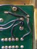
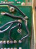
Here is a photo of the two brown wires from my 7070....
BIAS wires Mine.jpg
 
Thanks for confirming that the driver board needs to be installed. Yes, the VD1212 replacements are in series not parallel, my bad. The D07/D08 diodes are installed correctly.

So, I've made good progress, but have questions.

1. I adjusted the bias on both channels to 30mv, the DBT died down once these values were dialed down (properly)
2. DC offset is 0ma for both channels
3. Relay is clicking on when powered on!!!! It's taking about 8-10 seconds to click on, for now at least, I need more optimism. Another highlight, for me, is that there is NO smoke this time. :) So I think the time spent with the driver board was worthwhile. However,
4. I'm getting volume coming from both channels, but it is very faint. (the tone board is working properly as you can hear the adjustments, FM signal works (it drew in a very good signal without an antenna), I have yet to test the rebuilt phono board, will do that once I've addressed the faint volume level.
5. My meters are not working, I'm assuming that these will need to be reset per the SM 2.2 Power Meter adjustments. I've tried this previously and did not have luck with it, but will give it another go. Would this affect the volume output of the receiver or is this something else?
6. When setting the bias there are three pins (05,06,07) with two leads (03,04). Per the SM, Pin 5 is for the + lead and Pin 6 & 7 are for - leads for left and right channels to set the bias. From my pictures, I have lead 03 going to pin 07 and lead 04 going to pin 06. Can you please confirm which leads should be on those two pins? Asking, as I found another picture where the lead and pin combinations are different.
7. Any instruction on the Power Meters, would be most appreciated. Like I said, I'll give it another go.

So, I think that I'm getting closer to having a working unit. I look forward to your reply. Eagerly yours!!!
One more thing. Make sure you don't have a headphone adapter in the headphone jack. I once bought a receiver that the seller said "no sound", and guess why? :idea: Yep, the adapter in the jack had the speakers disconnected. :D
 
8 - 10 seconds is normal for these so that is fine. Make sure the TAPE PLAY is on SOURCE. It intercepts ALL input signals. Buttons - Audio muting OUT, Dolby adapter OUT, MPX OUT, FM Muting IN (for off).
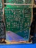
Here is a photo of the two brown wires from my 7070....
View attachment 2034901
After having to search for the function post for the tape source, I had forgotten that I pulled it out when I worked on the phono board. Anyway, it was found and installed and set to the tape output source. I put the leads onto pins 06, and pin 07 per your picture (I was able to confirm the same from my original pictures, albeit the leads were really dusty) the relay doesn't click on. However, If the pins are on 05 and 07 the relay clicks on?????? Any thoughts? I do shut the receiver down immediately after I hear the relay click with the leads on these two pins. ugh...so close. :)
 
Having a different board would be good but it can be repaired. Glue it with a cyanoacrylate glue and jump the traces with small wires.

- Pete
 
You can also scrape some of the coating off the traces and bridge each trace with some scrap capacitor leads(usually thicker than resistor leads), soldered to the traces. It's mainly to add strength to the joint, but will also electrically bridge the fracture. On this board I'd only do a couple of leads (mainly on the FAT trace and around the screw) and run wires for the rest.
 
No, you can work with it. However I would never let shipping gorillas anywhere near it. And that is probably what broke it in the first place. You might want to consider trying to find another main board. They are actually very easy to swap out in these. Being out makes it so much easier to clean and repair/rebuild. I do it with every 7070 I rebuild.
7070 Main Board Out.jpg
 
No, you can work with it. However I would never let shipping gorillas anywhere near it. And that is probably what broke it in the first place. You might want to consider trying to find another main board. They are actually very easy to swap out in these. Being out makes it so much easier to clean and repair/rebuild. I do it with every 7070 I rebuild.
View attachment 2035779

I did purchase the unit locally this past July but don't have a history of the unit prior to that. I went back thru my original pictures that I took of the unit for reference and I can see the crack in the board was there when I purchased it. Perhaps it has been there since it was manufactured, as it does look like there is some glue already on the board. I just didn't notice it until yesterday, when I was working on the unit.

Anyway, I priced out the glue that Pete recommended and it costs about a quarter of what the board does, plus I need to take into account my time needed to repair the board. I've found a replacement F-2625, so all in all, I think that ordering the new board makes more sense for me. It will hopefully, kill a few birds with one stone, as, I had planned to redo this board anyway and agree that it would be easier to refurbish out of the unit as you have pictured. Now, hopefully, the board that I've found is in good condition, pictures seem to indicate this. :)
 
I did purchase the unit locally this past July but don't have a history of the unit prior to that. I went back thru my original pictures that I took of the unit for reference and I can see the crack in the board was there when I purchased it. Perhaps it has been there since it was manufactured, as it does look like there is some glue already on the board. I just didn't notice it until yesterday, when I was working on the unit.

Anyway, I priced out the glue that Pete recommended and it costs about a quarter of what the board does, plus I need to take into account my time needed to repair the board. I've found a replacement F-2625, so all in all, I think that ordering the new board makes more sense for me. It will hopefully, kill a few birds with one stone, as, I had planned to redo this board anyway and agree that it would be easier to refurbish out of the unit as you have pictured. Now, hopefully, the board that I've found is in good condition, pictures seem to indicate this. :)
The glue Pete mentioned, is known as "Super Glue". I really doubt it came broken from the factory.. The glue on it was more than likely someone else's attempt at a repair. If you get the board out, and cleaned, you can super glue the crack, then bridge all the traces to reconnect them and have a "spare" for future use.. As long as the "new" board isn't broken, it can be "repaired" if need be out in the open. Just be careful when soldering so the traces don't lift on you. Use as little dwell time as you can to prevent over heating the traces and breaking their bond to the board.
 
The glue Pete mentioned, is known as "Super Glue". I really doubt it came broken from the factory.. The glue on it was more than likely someone else's attempt at a repair. If you get the board out, and cleaned, you can super glue the crack, then bridge all the traces to reconnect them and have a "spare" for future use.. As long as the "new" board isn't broken, it can be "repaired" if need be out in the open. Just be careful when soldering so the traces don't lift on you. Use as little dwell time as you can to prevent over heating the traces and breaking their bond to the board.
The replacement board has been ordered, hopefully, will have it before the end of the week. I'll post an update when I receive the board. Once, received, I'll assume that I can begin to replace the caps, install the new relay, new filter caps (Nichicon FG 10000uf 63v, snap-in, which I'm assuming will be ok?), etc, and then fit the board into the receiver? Or is there another recommended process?
 
The replacement board has been ordered, hopefully, will have it before the end of the week. I'll post an update when I receive the board. Once, received, I'll assume that I can begin to replace the caps, install the new relay, new filter caps (Nichicon FG 10000uf 63v, snap-in, which I'm assuming will be ok?), etc, and then fit the board into the receiver? Or is there another recommended process?
Put the main filter caps in after the board is installed. They won't fit through the openings in the chassis. Screw the clamps into position before you solder the caps too so the holes align. I usually have the clamps on just "snug" so I can move them to align the holes. Then pull the cap w/ clamp out and tighten them, recheck and adjust if necessary, screw the clamps down, then solder the connections. It's a little "tight" down there behind the transformer. BUT, before the main caps, be sure to solder the speaker negative wires. They are right between the filter caps.
 
Put the main filter caps in after the board is installed. They won't fit through the openings in the chassis. Screw the clamps into position before you solder the caps too so the holes align. I usually have the clamps on just "snug" so I can move them to align the holes. Then pull the cap w/ clamp out and tighten them, recheck and adjust if necessary, screw the clamps down, then solder the connections. It's a little "tight" down there behind the transformer. BUT, before the main caps, be sure to solder the speaker negative wires. They are right between the filter caps.

Hi, thanks for telling me about the filter caps and the neg speaker wire install. You just saved me a bunch of time and aggravation. I'll take all the tips that I can get!! Keep'em coming. :) I received the F-2625 board, other than a slightly lifted pad for (ironically, it's the negative speaker wire), it looks good. I'm planning to tend to the pad, clean the dust and grime off the board, and proceed with replacing, in order, the caps, transistors, relay, and install the new filter caps per your instructions. I'm looking forward to this and am hopeful that it's a step in the right direction, if not the solution. More to come...
 
Hi, thanks for telling me about the filter caps and the neg speaker wire install. You just saved me a bunch of time and aggravation. I'll take all the tips that I can get!! Keep'em coming. :) I received the F-2625 board, other than a slightly lifted pad for (ironically, it's the negative speaker wire), it looks good. I'm planning to tend to the pad, clean the dust and grime off the board, and proceed with replacing, in order, the caps, transistors, relay, and install the new filter caps per your instructions. I'm looking forward to this and am hopeful that it's a step in the right direction, if not the solution. More to come...
The negative speakers go to ground anyways so you can just bend the one wire over through it's lifted trace to the other one and tie them both together with solder. Speaker Negative wires on main board trace.jpg
 
Back
Top Bottom