• The move to the new server is done. There are some software and database maintenance updates in process. This has us passing the hat around to help out. We appreciate any donations. Seriously, even a dollar helps. The payment page may be found here - https://www.audiokarma.org/support.html

Correct Output transistor replacements for Sansui 7070

I'm getting my ducks in a row for working on the F-2625 board and had a couple of questions.

1. On my 7070 BOM list there is a line item for a cap at C15 a 47uf 50v. I have the cap, but I don't see the cap on the board. There is a resistor that is running across from I believe the positive side of the cap, both the original board and the replacement board are like this. Was there a variation of this board with the cap at C15 or is this a modification? I can see from your picture of the board, that the cap is missing as well. So, I likely shouldn't be concerned about C15.
2. I was planning on replacing TR03, and TR04 which are C945s with 2383's. I had planned to leave TR01 D438 & TR02 B560, do these need to be swapped out? If so, what would be the correct Q's to replace them? B560 = KSA916YTA / D438=KSC2316 both TO-126?
3. I will replace the fuse resistors at R04 with 100 1/2 watt & R27, R28, R29, R33, R34 with 4.7 1/2 watt resistors.
4. Are there any other diodes or resistors that should also be replaced on the board?
5. Regarding the relay, it appears that you kept the mounting shell and replaced the original relay with the replacement? This is what I'm planning on.
6. In Post #11 there is black wiring on the backside of the board, these are not on the replacement board. It appears that they have been clipped off (?) I'm assuming that these should be replaced during the rebuild or are they not original to the board and possibly used to repair the original board? If they should be part of the rebuild what gauge replacement wire would you recommend? I believe that I have 18, 20, 22, & 24 gauge. I can use my pictures as a reference.
7. When removing the original board, should I remove the filter caps 1st? Based on your prior comments I'm assuming that the board will be difficult to get out without them being removed.
8 Other?

Ok, so more than a couple of questions. thanks, in advance.
 
I'm getting my ducks in a row for working on the F-2625 board and had a couple of questions.

1. On my 7070 BOM list there is a line item for a cap at C15 a 47uf 50v. I have the cap, but I don't see the cap on the board. There is a resistor that is running across from I believe the positive side of the cap, both the original board and the replacement board are like this. Was there a variation of this board with the cap at C15 or is this a modification? I can see from your picture of the board, that the cap is missing as well. So, I likely shouldn't be concerned about C15.
2. I was planning on replacing TR03, and TR04 which are C945s with 2383's. I had planned to leave TR01 D438 & TR02 B560, do these need to be swapped out? If so, what would be the correct Q's to replace them? B560 = KSA916YTA / D438=KSC2316 both TO-126?
3. I will replace the fuse resistors at R04 with 100 1/2 watt & R27, R28, R29, R33, R34 with 4.7 1/2 watt resistors.
4. Are there any other diodes or resistors that should also be replaced on the board?
5. Regarding the relay, it appears that you kept the mounting shell and replaced the original relay with the replacement? This is what I'm planning on.
6. In Post #11 there is black wiring on the backside of the board, these are not on the replacement board. It appears that they have been clipped off (?) I'm assuming that these should be replaced during the rebuild or are they not original to the board and possibly used to repair the original board? If they should be part of the rebuild what gauge replacement wire would you recommend? I believe that I have 18, 20, 22, & 24 gauge. I can use my pictures as a reference.
7. When removing the original board, should I remove the filter caps 1st? Based on your prior comments I'm assuming that the board will be difficult to get out without them being removed.
8 Other?

Ok, so more than a couple of questions. thanks, in advance.
1. Many a "BOM" will be for a specific unit and are many times different than what you have. Only replace the parts/values that are originally in yours UNLESS there was a known change. Make your "replacement" board the same as your original board.
2. The relay was in "perfect" condition so I left it in. If your points look "dark" or anything other than bright and shiny, replace it with an Omron.
3. Yes, those black wires were the "repair" used to reconnect the broken traces. You can ignore them.
4. Just replace the fusible resistors unless any of the others are burned or suspect.
5. If the legs on the transistors are blackened, I would change them. The KSA916Y (for the B560) is a TO-92L (longer than a standard TO92). It's compliment is the KSC2383Y (D438) and is also a TO-92L. The 2SC945 can be KSC945CYTA. The C stands
for Center Collector like the original. But the KSC2383 will still be fine there.
6. Well DuH, yes remove the main filter caps first (and the speaker negative wires) to remove your board from the chassis. :D
 
1. Many a "BOM" will be for a specific unit and are many times different than what you have. Only replace the parts/values that are originally in yours UNLESS there was a known change. Make your "replacement" board the same as your original board.
2. The relay was in "perfect" condition so I left it in. If your points look "dark" or anything other than bright and shiny, replace it with an Omron.
3. Yes, those black wires were the "repair" used to reconnect the broken traces. You can ignore them.
4. Just replace the fusible resistors unless any of the others are burned or suspect.
5. If the legs on the transistors are blackened, I would change them. The KSA916Y (for the B560) is a TO-92L (longer than a standard TO92). It's compliment is the KSC2383Y (D438) and is also a TO-92L. The 2SC945 can be KSC945CYTA. The C stands
for Center Collector like the original. But the KSC2383 will still be fine there.
6. Well DuH, yes remove the main filter caps first (and the speaker negative wires) to remove your board from the chassis. :D

As always, thanks for the advice and instruction. I've kinda found out that a BOM is like a service manual, can't always trust'em. (I did pick up a Marantz Model 26 manual last week which had a like new supplemental parts list and schematics on a blueprint paper or type of paper. it's very cool. well find out at a future date how they compare.) Happy to ignore the broken trace wires. :banana: Ok, on the fuse resistors, understand about the caps, but some of the replacements will have a slightly higher value? (i.e. 1000uf 100v replacing a 1000uf 80v) It's what I have on hand for it. Yeah, the transistors are blackened, so I will have to change them out. I'm pretty sure that I have the KSC2838Y and the KSC945CYA, but will need to order the KSA916Y. I'll just replace the caps and wait until I have all the transistors in hand. Yeah, I have my DuH moments like that. :crazy: At least that's what my better half tells me. To much time sitting in front of my computer studying these days and not enough time attending to fixing this girl. We'll get there. :)
 
As always, thanks for the advice and instruction. I've kinda found out that a BOM is like a service manual, can't always trust'em. (I did pick up a Marantz Model 26 manual last week which had a like new supplemental parts list and schematics on a blueprint paper or type of paper. it's very cool. well find out at a future date how they compare.) Happy to ignore the broken trace wires. :banana: Ok, on the fuse resistors, understand about the caps, but some of the replacements will have a slightly higher value? (i.e. 1000uf 100v replacing a 1000uf 80v) It's what I have on hand for it. Yeah, the transistors are blackened, so I will have to change them out. I'm pretty sure that I have the KSC2838Y and the KSC945CYA, but will need to order the KSA916Y. I'll just replace the caps and wait until I have all the transistors in hand. Yeah, I have my DuH moments like that. :crazy: At least that's what my better half tells me. To much time sitting in front of my computer studying these days and not enough time attending to fixing this girl. We'll get there. :)
Good with the 80volt caps going to 100volt. No problem there. I do it often. The "value" is the same at 1000uf. :biggrin: I have plenty of :rolleyes: moments myself. If I took video, I could have a 2 hour long "DuH" video of 10 second clips. :rflmao:
I just rebuilt a Marantz 22 and it was quite a task. I employed many of the 22R (revised) changes into it as I went from the service bulletins. This one was an earlier serial number from the "R" version before all the factory changes but already had a few factory revisions in place. Man that thing sounded so sweet and detailed when it was done. It had a problem in the tuner and ended up being the MPX decoder chip. After a week or two search I found one. The tuner is very good in it once fixed. What is kind of cool is the decoder chip was made only 20 minutes away and made it's way back "home" years later. It was made at ECG Sylvania plant in Williamsport, Pa. The owner of the 22 is only 10 minutes away from there. If the 26 is anything like that, you'll be very pleased with it.
 
Good with the 80volt caps going to 100volt. No problem there. I do it often. The "value" is the same at 1000uf. :biggrin: I have plenty of :rolleyes: moments myself. If I took video, I could have a 2 hour long "DuH" video of 10 second clips. :rflmao:
I just rebuilt a Marantz 22 and it was quite a task. I employed many of the 22R (revised) changes into it as I went from the service bulletins. This one was an earlier serial number from the "R" version before all the factory changes but already had a few factory revisions in place. Man that thing sounded so sweet and detailed when it was done. It had a problem in the tuner and ended up being the MPX decoder chip. After a week or two search I found one. The tuner is very good in it once fixed. What is kind of cool is the decoder chip was made only 20 minutes away and made it's way back "home" years later. It was made at ECG Sylvania plant in Williamsport, Pa. The owner of the 22 is only 10 minutes away from there. If the 26 is anything like that, you'll be very pleased with it.


I've not heard the 22 but have read really great things about it. The 26 sounds really great, but she needs some love. I was fortunate to find an original cabinet for it as well for a very reasonable price, it's a bit rough but will give me the opportunity to learn how to work with wood veneer. Another hole to jump into. I believe that the 26 was one of the last designs that Saul Marantz personally designed before selling the company. Fun story about the decoder chip. It's crazy how small a world we really live in. Learning about the history of a piece of gear that you come to own is always part of the fun in this hobby.

Was able to get some time in on the board only the transistors need to be replaced. Putting together a Mouser order, needed to add a few things other than ordering a single $10 transistor. ;) I have an SR-636 to pair with the 7070. I've been planning to refurbish the table as it has a couple of quirks, that need to get resolved to get tip-top. Just finished up the BOM for it, so hopefully, get this ordered up tomorrow. While waiting for the parts, I'm thinking that I will remove the original board from the chassis. I'm getting the sensation of me taking a boatload of pictures. More to come...hope that you had a good turkey day.

3FD2C32A-9BEA-4097-BD86-F07C99648C2D.jpeg
 
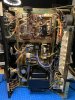
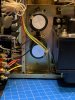
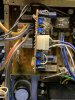
Well, I've passed my state and national real estate exams, but I still, have one course to complete. So as a reward, I finally made some time to work on the 7070. Here is my update...I removed the old filter caps in preparation to remove the old F-2625 board (thank you for this tip), then was able to install the new rebuilt board. I reinstalled the main filter caps with new Nichicon KG 10000uf 63v. The clamps were larger than the new cap, which I figured would be the case. I have 35 mm brackets, but they didn't align with the screw holes. So, I wrapped a strip of foam insulation (weather stripping) and then wrapped it with electrical tape, it fits the original brackets snugly. The caps are snap-in, so I wire-wrapped them to extend the lead so that I could fold it over onto the board for soldering. Yes, I installed the negative speaker wires first (a thank you, thank you for that tip), it would have been a nightmare otherwise. Reassembled the wiring, installed the PSU and driver boards, plugged it into the DBT, and fired it up and no relay click. Joy. Removed the board, relay clicks. Ok, so I'm back to the board. Went thru it with the meter first and then redid several solders. Replaced the board and fired it up, and the relay clicks!!! :banana: Yes, plugin iPod to test, and there is no output from either channel until you turn the volume all the way up. Sounds great, just isn't doing what it needs to. I have adjusted the DC to 0V on both channels, the bias is set at ~30.5 ma on each channel. However, I'm haven't figured out the power meter adjustment. I was having an issue with the meters not working properly. I went thru the eq board with a meter all looked ok, I did have a pad come off, which I repaired and the circuit checked out. Once, that was done, I started to get movement in both meters. So, the good news is that the relay now clicks and I'm getting movement in the meters :), but there is still a faint sound coming from both channels. :( So, I know need to figure out why the sound output is not working...:confused:.

F78B6B6E-62DD-4697-A595-19D06E4CFD31.jpeg 7FE0299A-BFB0-4DE1-8D2D-31A40EB80C8F.jpeg 93E5853D-0F39-473E-9C2E-4BAA28F029B4.jpeg
 
Well, I've passed my state and national real estate exams, but I still, have one course to complete. So as a reward, I finally made some time to work on the 7070. Here is my update...I removed the old filter caps in preparation to remove the old F-2625 board (thank you for this tip), then was able to install the new rebuilt board. I reinstalled the main filter caps with new Nichicon KG 10000uf 63v. The clamps were larger than the new cap, which I figured would be the case. I have 35 mm brackets, but they didn't align with the screw holes. So, I wrapped a strip of foam insulation (weather stripping) and then wrapped it with electrical tape, it fits the original brackets snugly. The caps are snap-in, so I wire-wrapped them to extend the lead so that I could fold it over onto the board for soldering. Yes, I installed the negative speaker wires first (a thank you, thank you for that tip), it would have been a nightmare otherwise. Reassembled the wiring, installed the PSU and driver boards, plugged it into the DBT, and fired it up and no relay click. Joy. Removed the board, relay clicks. Ok, so I'm back to the board. Went thru it with the meter first and then redid several solders. Replaced the board and fired it up, and the relay clicks!!! :banana: Yes, plugin iPod to test, and there is no output from either channel until you turn the volume all the way up. Sounds great, just isn't doing what it needs to. I have adjusted the DC to 0V on both channels, the bias is set at ~30.5 ma on each channel. However, I'm haven't figured out the power meter adjustment. I was having an issue with the meters not working properly. I went thru the eq board with a meter all looked ok, I did have a pad come off, which I repaired and the circuit checked out. Once, that was done, I started to get movement in both meters. So, the good news is that the relay now clicks and I'm getting movement in the meters :), but there is still a faint sound coming from both channels. :( So, I know need to figure out why the sound output is not working...:confused:.

View attachment 2057921 View attachment 2057922 View attachment 2057923
Make sure the switches are set right, and nothing is in the headphone jack.
 
Make sure the switches are set right, and nothing is in the headphone jack.

Yup, switches are set to source output. I've used both headphones and speakers (without the headphones inputted) to test and got the same result faint sound coming from both channels, but only at max volume. The meters are showing some sign of life, but are not registering the power output as it should. Could this be causing the faint sound? I've already replaced the original output transistors, so I don't believe that the issue lies there, but what do I know. Not quite sure where to go from here???? o_O
 
Yup, switches are set to source output. I've used both headphones and speakers (without the headphones inputted) to test and got the same result faint sound coming from both channels, but only at max volume. The meters are showing some sign of life, but are not registering the power output as it should. Could this be causing the faint sound? I've already replaced the original output transistors, so I don't believe that the issue lies there, but what do I know. Not quite sure where to go from here???? o_O
The meters have no effect on the output and only reflect the power output. Try using the FM tuner instead with the MUTE switch IN (for FM muting OFF). You should hear the FM "hiss" if no station is tuned in.
 
The meters have no effect on the output and only reflect the power output. Try using the FM tuner instead with the MUTE switch IN (for FM muting OFF). You should hear the FM "hiss" if no station is tuned in.

I switched over to the FM tuner from the AUX input. I do get a higher level output when on FM (either FM or FM Dolby), I do get a hiss when the FM muting is switched IN and clear reception on stations that is dialed in. Now, a few things of interest, after doing this.

1. When the FM muting switch is in the IN position, the FM Stereo light does not shut off (it should with the FM muting switch engaged?).
2. When adjusting the volume the FM Stereo light disappears and the signal drops, a second or two later it comes back on (light and sound).
3. Same for the tone controls (they are working as I can hear them adjust), but the FM Stereo light disappears and the signal drops, a second or two later it comes back on (light and sound).

Thoughts?
 
I switched over to the FM tuner from the AUX input. I do get a higher level output when on FM (either FM or FM Dolby), I do get a hiss when the FM muting is switched IN and clear reception on stations that is dialed in. Now, a few things of interest, after doing this.

1. When the FM muting switch is in the IN position, the FM Stereo light does not shut off (it should with the FM muting switch engaged?).
2. When adjusting the volume the FM Stereo light disappears and the signal drops, a second or two later it comes back on (light and sound).
3. Same for the tone controls (they are working as I can hear them adjust), but the FM Stereo light disappears and the signal drops, a second or two later it comes back on (light and sound).

Thoughts?
First, does the volume sound "normal" now?
The FM muting cuts out the "hiss" between stations to be less annoying. I am not sure but the FM stereo light will still be on when tuned to a strong station. FM Muting is not FM Mono. It is not uncommon for stereo to drop out if the incoming signal is unsteady and signal drops below the threshold. But the tuner may need an alignment to tweak it to full potential and synchronize the tuning meters. It is also possible there is an issue in the tuner such as a leaky cap, transistor, diode, or even an IC starting to misbehave. That would take some expertise and proper equipment to diagnose and repair. But it may just be completely a signal strength issue of the stations and nothing may be wrong. :dunno: FM can be different between stations and exhibit different stereo behaviors. I have a close station with very strong signal, but the stereo drops in and out and is very noisy. But another station some 40 miles away (same direction) with a weaker signal that comes in stereo very clear.
 
No, the volume is not normal. It improved slightly, with the usage of the tuner, but it is still at max volume, and it is not putting out a deafening sound. I know and understand what you are describing when a station is tuned in and the signal gets "hissy" and then returns. Not like when you have a steady signal, and the station becomes distorted and then back to stereo. It's certainly possible that there could be an issue with one of the caps on the tuner. I've planned to recap the tuner, but not replace the transistors as I understand that this will then require the tuner to be realigned. I don't have the equipment nor the expertise to do this. So, what you are describing isn't what I'm seeing. I just went back to look at it again, the signal strength is very strong, however, once I just TOUCH or turn the volume control, any of the tone controls, and just discovered the same with the mic control the signal drops for a second or so and came back strong as it was before. Just by touching the pots, this ONLY happens when the FM Dolby or FM inputs are selected, none of the other inputs exhibit this.

Also, when I turn the unit on (I have it on the DBT) the bulb lights up, and then immediately dims. When I have FM or Aux selected (I'm assuming that this is the same for the phono as well, but am not sure as I don't have a table hooked up. I can do this if suggested, actually, I will do this today and see what happens as I did experience issues with the phono inputs after rebuilding the eq board) and am outputting from the speaker A connection, the bulb does get brighter. I'm assuming that this is due to the power being pushed to the speaker outputs? Now, I have replaced the original speaker terminals with banana terminals. I did this early on when I initially rebuilt the driver board and prior to rebuilding the eq board the receiver was working normally and had no problems with output from speaker A or B. Also, another thing that I just noticed is both the high and low filters don't seem to adjust when selected?? So, I'm thinking that there is still an issue with the eq board. I did check the eq board with a meter last night to test for the continuity in the circuits, it appeared to be good, but it is possible that I missed a circuit. I can look at it again.

So, I'm curious about the following options:

1. I've cleaned the controls previously, would it be worthwhile to do this again for the volume and tone control pots?
2. Revisiting and potentially rebuilding the EQ board or do you think that the tuner is the cause. I do feel as if the alignment is ok on the tuner based on how the signals are coming in tune, it's the weird effect that is happening with the control adjustment.
3. Could there be an issue with the tone board? Would it make sense to rebuild this board along with the PSU F-2626 board?

I'm thinking that the eq board is where the issue is and that I should look at this before considering #3. :idea:
 
Sounds suspiciously like the "TAPE MONITOR" is ON. Flip the Tape monitor switch to the position opposite it's current position. Make sure the volume is down 1st.
 
a quick update, I found the issue related to touching the controls and having the FM signal drop...making all of the connections to the F-2625 board are a good thing to do...I missed installing the green lead, which I'm assuming is coming from the tuner board. Anyway, one issue resolved....:)816EF6FC-FF48-4B5F-9CD4-F778CE211BD5.jpeg
 
Tested both Phono inputs and am only getting sound from the right channel on either Phono 1 or Phono 2....so I'm going to turn my attention to the eq board. I'll go thru the board with a meter, but will likely just plan to rebuild the board. I have found this board fairly difficult to access, any suggestions on how to best get at it would be helpful.

I'm suspecting that I have a transistor or cap oriented incorrectly. I'll post an update once I've delved into the board.
 
Worked on the eq board last evening and part of this morning, have started to reassemble, still need to reinstall the tone board into chassis (so the unit is entirely grounded) and then will fire her up and see whether or not the left channel of the phono inputs is working.

A couple of observations, after working on the eq board.

1. When I start the unit, the relay clicks almost immediately upon startup, previously it would take 6-10 seconds which I believe is normal, but was surprised about this change.
2. The sound output has increased in both channels, the sound is coming from both channels, still, not at the normal volume level, it should be, but has improved from where it was yesterday.
3. When I plugged in my headphones to test, I could hear what I would describe as a hiss or the presence of a stronger signal.

Once, I get the tone board installed and a turntable hooked up. I'll post another update. Hopefully, I'm on the right path.
 
Worked on the eq board last evening and part of this morning, have started to reassemble, still need to reinstall the tone board into chassis (so the unit is entirely grounded) and then will fire her up and see whether or not the left channel of the phono inputs is working.

A couple of observations, after working on the eq board.

1. When I start the unit, the relay clicks almost immediately upon startup, previously it would take 6-10 seconds which I believe is normal, but was surprised about this change.
2. The sound output has increased in both channels, the sound is coming from both channels, still, not at the normal volume level, it should be, but has improved from where it was yesterday.
3. When I plugged in my headphones to test, I could hear what I would describe as a hiss or the presence of a stronger signal.

Once, I get the tone board installed and a turntable hooked up. I'll post another update. Hopefully, I'm on the right path.

Ok, reinstalled the tone board and got a turntable hooked up, and viola....I have stereo coming from both channels on phono 1 and phono 2. :) I'm pretty sure that the issue was related to 2 solder pads that lifted off the board at C02 on F-2620. I removed the cap and repaired the solder pads using a copper foil with adhesive. I gently scraped off any residue from the pad locations, then cleaned with alcohol, next I (one had 1/2 of the pad the other was missing entirely) cut a sliver of the copper laid it over the trace line, then cut another piece of copper paper (I came up with the idea of using an old belt punch, which worked great as it punched out uniform circles to place over the pad) to place over the copper on the trace and then added solder over the joints of the copper for the pad and the copper sliver over the trace. Punched a hole thru the copper foil for the lead, installed a new Nichicon 10uf 25v KW cap at C02, and replaced another at C01 (believe this is the right location) with the same type cap, and soldered them in. Checked the continuity of the 2 repairs with my DMM, and had a tone on both circuits. I'm thinking good thoughts, fired her up, and the unfortunate part is that it's still the faint output that could only be heard at max volume thru either the headphones or speaker outputs. o_O Anyway, I was able to address the missing channel on the phono stage, so another issue crossed off my list of issues... :banana:I was then decided to adjust the DC and bias but remembered that I still needed to swap out 4 Q's on F-2625. I was finally able to order the needed transistors from mouser, I have two future projects (SONY TA-1144 Integrated (1970) and a SONY 2251 DD turntable (1971-74) that I ordered parts for as well. I didn't want to spend 4x the amount on shipping $2.00 worth of transistors. So, I loaded the cart. ;) With parts in hand, I replaced TR01 2SD438 with a 2SC2383, TR02 B560 with a 2SC916 (this was the needed transistor), and then TR03 and TR04 both 2SC945's with a 2SC945YTA's. Pulled the Q's one at a time, (once pulled, I checked them on my transistor checker to confirm pin locations and measurements), and started the unit (without F-2624 & F2626 boards removed), relay clicks, onto the next one. Replace TR02, restarted unit, relay clicks again, good. Next TR03, C945 replaced with C945YTA, restarted unit, relay clicks, yay! One to go, pulled TR04 2SC945 checked on transistor checker, and this transistor is not recognized, bad part...checked on my second tester with same results. Ok, replaced TR04 with new 2SC945YTA, restarted the unit...NO relay click. :yikes: Reflowed my solder on the Q and found a small solder bridge. Restarted the unit, and the relay clicks. Phew! Installed F-2624 and F-2626, restarted the unit, and the relay clicks...:jump: Ok, the next thing I did was to adjust the DC and the Bias current. Started with the left channel per SM, DC was reading -.56 V, was able to adjust to 0V +/- 10mV, next adjusted the Bias it was 76mA, adjusted to 30.5 mA. Turn to the right channel to do the same adjustments, had a DC reading of -.57, was able to adjust to 0V +/- 10mV, next up the bias, this is where I run into an issue...as the bias would not adjust on the right channel? I thought that I was one step closer...anyway decided to start the unit to see whether there are any changes to the output volume. I had the FM input set, and after fiddling with the volume control (I did retreat all the pots while the eq and tone boards were removed) I came to the conclusion that something is not working right. I was adjusting the volume control and didn't hear any change...well another "duh" moment, I realized that I had my 2000X playing the same station...aha...you dummy. Shut off the 2000X and the next thing I know I have sound coming out of both left and right channels. :biggrin: However, the sound is crystal clear on the left channel and is distorted on the right channel with slightly less volume (which I'm assuming is due to the distortion). I'm also guessing that the bias current not properly adjusted is the cause of the distortion? But, wait, a new issue is that as I turn up the volume, the meters start to work at the 9:00 o'clock position, I've been able to get the volume past 1-2 o'clock, so the output is much stronger, the right channel still distorted, left is good, but as I turn down the volume, the relay then clicks off at about 11:00 o'clock. :wtf:

So, I'm looking for some ideas/assistance/input on how to address the DC, Bias current adjustments on the right channel (would this be associated with the F-2624 board?) or could this be due to a PSU issue on the F-2626 board? Also, comments on the relay clicking off as the volume is turned down. I had initially thought that the unit was clipping as the volume was turned up I didn't go past the 2:00 position, it started to get really loud on my test speakers, and didn't want to wake anyone this morning, so it's possible that it could be happening, but am not sure. Still not sure why the relay clicks off when the volume is turned down? I forgot to mention, that the relay does click back on after the volume adjustment stops and the sound returns to both channels. :confused:

Could the relay, be part of the problem? I have not cleaned it, if I need to remove to clean, I would likely just replace it with a new relay that I have for it. Regarding the bias and DC adjustments for the right channel would this be addressed on the F-2624 board or could the issue lie with the F-2626 board (it has not been rebuilt)? I am also planning to rebuild the tone board, should I wait on this or can I go ahead with rebuilding this board? I know that the tone controls are working, and I'm assuming that the bias and DC issue is not related to this board. I have not forgotten the "golden rule" of working one board/issue at a time. Just looking to get my ideas out. Apologies, if I've repeated myself in this post. I feel like I'm close to resolving the primary operating issues that I've been having and hope that I can get this resolved so I can finish the rebuild, put the cover on, and start rocking...:music:
 
First, does the volume sound "normal" now?
The FM muting cuts out the "hiss" between stations to be less annoying. I am not sure but the FM stereo light will still be on when tuned to a strong station. FM Muting is not FM Mono. It is not uncommon for stereo to drop out if the incoming signal is unsteady and signal drops below the threshold. But the tuner may need an alignment to tweak it to full potential and synchronize the tuning meters. It is also possible there is an issue in the tuner such as a leaky cap, transistor, diode, or even an IC starting to misbehave. That would take some expertise and proper equipment to diagnose and repair. But it may just be completely a signal strength issue of the stations and nothing may be wrong. :dunno: FM can be different between stations and exhibit different stereo behaviors. I have a close station with very strong signal, but the stereo drops in and out and is very noisy. But another station some 40 miles away (same direction) with a weaker signal that comes in stereo very clear.


A quick update, I've got volume coming out of both channels, however, the right channel is distorted and I can't figure out where the issue is. I pulled R21 and R22 on F-2625 (based on a previous string) and they are ok within range. I've also replaced the relay, this did not affect the distortion but is clicking on as it should. The meters are moving when the volume is turned up. I am planning to recheck the DC and the bias current later today. I've been able to set the bias on the left channel but not the right channel, I'm assuming that this is the issue or part of it? I've cleaned up solders on the EQ board, redid the soldering to the speaker terminals. I am getting sound out from both speaker A and B outputs, the right channel is distorted on both outputs. I also cleaned all of the pots again, no change to right channel. I'm contemplating the following...rebuild of the tone board. I know that this is working, as I can hear the bass, mid, and treble adjust thru both speakers. Additionally, based on other strings, that I'll also likely rebuild the F-2626 board as well. Anyway, any feedback is appreciated. Thanks to everyone who's jumped in in this string.
 
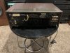
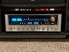
All done. For a newbie (started to learn how to do this April 2020), this was a challenging learning experience, but it was worth every minute. Thanks to those who helped, it provided great direction for me to figure out how to finally get it working. The rush you get when you hear the music come pouring out of your speakers is hard to beat, particularly when you hear an immediate difference in how the receiver sounds compared to before being rebuilt!

A488363A-2DA8-4C21-993F-4F5CEABF5011.jpeg D76BDF6B-6836-47BA-998A-EBCFE58D6993.jpeg E944E782-F989-4652-BD1C-01E0E6027B97.jpeg
 
Back
Top Bottom