• The move to the new server is done. There are some software and database maintenance updates in process. This has us passing the hat around to help out. We appreciate any donations. Seriously, even a dollar helps. The payment page may be found here - https://www.audiokarma.org/support.html

Correct Pin-Out on SX-850 Protection Relay

Well, I am glad it is fixed, I may have finally nailed it, but we did a bunch of hammering. Markthefixer was on the right track with power supplies while you and he were looking over the Protection circuit.
You are most welcome, I enjoyed the learning opportunity!
ENJOY!
 
Actually, if you have to order parts, and have not rebuilt the power supply, that is where i would go next. C10 is the filter for the input to the +51.5 regulator, C11 for the -51.5 regulator. Both of those, and C15, C16, C18, C19, C20, C21, C12, C13, C14.

How much work and expense are you wanting to put into this unit? We are getting into refurbish territory for effort and expense. Simple fix/repair is less work and expense now, but maybe more later. Refurbish (I like that word better than 'recap') is more work and immediate expense now, but likely means longer term function and reliability. Your unit, your time, and your money, so you tell me which way you want to go about it . . .

Your point is well taken. The short answer is the expense is not so much the issue as the time.

Originally, I had intended only to clean it up and enjoy it, and possibly do a few minor repairs if necessary. Quite honestly, if it had not been an SX850 (and an especially minty one!), I would probably would have given up on this "pop" issue and broomed it.

The Protection Board was re-done earlier, as a first attempt to fix the pop. It was a full "refurb" with caps, transistors, diodes, zeners. But now that the Flat Amp and Power Supply boards have been partially disassembled and are accessible, I plan to "refurb" them as well. I've already submitted an order for new caps, transistors, etc.... Not sure yet if I'll change the transistors, but at least I'll have them on hand. At that point, if everything is working well, I will probably leave the other boards. :-)

By the way, what do you think about the dramatic difference in audible hum, between channels, when touching the pre/out jumpers (ref. post #27). I'll re-verify it's there, after completing the Flat Amp and Power Supply boards. But doesn't seem related to the "pop" noise. I'll start a NEW thread on this problem, if it's still there.

Thanks, again, for all your excellent (and patient) help!! :beerchug:
 
Your point is well taken. The short answer is the expense is not so much the issue as the time.

Originally, I had intended only to clean it up and enjoy it, and possibly do a few minor repairs if necessary. Quite honestly, if it had not been an SX850 (and an especially minty one!), I would probably would have given up on this "pop" issue and broomed it.

The Protection Board was re-done earlier, as a first attempt to fix the pop. It was a full "refurb" with caps, transistors, diodes, zeners. But now that the Flat Amp and Power Supply boards have been partially disassembled and are accessible, I plan to "refurb" them as well. I've already submitted an order for new caps, transistors, etc.... Not sure yet if I'll change the transistors, but at least I'll have them on hand. At that point, if everything is working well, I will probably leave the other boards. :)

By the way, what do you think about the dramatic difference in audible hum, between channels, when touching the pre/out jumpers (ref. post #27). I'll re-verify it's there, after completing the Flat Amp and Power Supply boards. But doesn't seem related to the "pop" noise. I'll start a NEW thread on this problem, if it's still there.

Thanks, again, for all your excellent (and patient) help!! :beerchug:

You are most welcome!
Fixing the large hum when touching the jumper may be a long project. It could be as simple as seeing a broken ground wire or as difficult to find as an open small cap 'somewhere'.
As to the refurb process, I would do the troublesome transistors and polarized caps at minimum. However, once you have gone to all the time and effort to gain access, why not do it thoroughly. That is what happened to me when I went to repair my SX-1050. I bought a fairly comprehensive list of parts from a BOM here on AK and dug into it. I found the primary failure fairly quickly, one of the main supply caps (22,000µF, 80v) was open. After that it would sing again. Then I started in on the protection and power supply boards. I almost did not change the protection relay, but decided since I had it, and was already in there, I would go ahead and do it. I disassembled the old one and found much more damage that I expected. Burnt and misaligned contacts. Made me glad I had changed it. Started on the power supply regulator, tested each part as it came out, found several electrolytic caps completely open, so I ended up being glad I dug into that also. Next I am into the Flat amp - started changing parts and decided to put film caps in place instead of the electrolytics. Lo and behold, some of the caps in the signal path are tantalums, known for trouble, so out they go, replaced with film caps (from another parts order). I am ending up doing a thorough refurbish, instead of a patch and fix, just could not pass up the opportunity to "do it right". My OCD perfectionism strikes again. I hope it lasts for another 43 years!
Some AK links:
Top Ten Worst Transistors - noisy, failure-prone, whatever... and replacements
Low Noise Small Signal Transistors
Bipolar Junction Transistor Testing Basics
Pioneer Tuning Fork Service Guide
The Idiot's Guide to Using DeOxit (revisited)
While I have worked many years in electronics, much of the 'Pioneer' I have learned here on AK is from markthefixer's threads.
 
Well, I am glad it is fixed, I may have finally nailed it, but we did a bunch of hammering. Markthefixer was on the right track with power supplies while you and he were looking over the Protection circuit.
You are most welcome, I enjoyed the learning opportunity!
ENJOY!

Well, I hope you meant it, about enjoying the learning experience... Because IT's BACK! Yes, I'm both frustrated and embarrassed to admit it, but the power-off speaker pop is back!

This is after replacing all the temp caps we used for troubleshooting in Flat Amp and Power Supply with the new Nichicon caps that I ordered.

A new clue.... it turns out it may not ALWAYS be there. A couple of times, out of maybe 30 tries, it did not pop. The rest of the time, it made the same volume-sensitive pop that we were chasing for weeks. Is that a change from before? I'm not sure, because it seemed completely repeatable before. ARGH! I'm pulling out what little hair I still have!:(:(

Reminder/Summary of replaced parts:
Protection board: all caps, all transistors, all diodes
Flat Amp: all electrolytic caps, all transistors
Power Supply: all electrolytic caps

I have new transistors for the Power Supply, but have not installed them yet, pending your comments and advice. I do know from other threads that there are several that can be troublesome.
 
OK, well, more learning!
You hear the pop after the protection relay pulls in, correct? How much time between the two events?
What is the dc voltage on the collector of Q1? Measure ac ripple also. DCV on the cathode of ZD11? Measure before making any other changes.
On the power supply you did change C16? Change Q1 and Q3. Pull FU1 and FU2 and test them, then test D1, D2, D3, D4. You will probably need to lift one end of those diodes to get a good test or If you have 1N4004 or UF4004 diodes just replace D1 - D4. Deoxit the fuses and holders before you reinstall fuses.
 
OK, well, more learning!
Thanks for not ghosting me. Wouldn't blame you if you did. Here's the responses to your questions/directions, with some added comments at the end...

You hear the pop after the protection relay pulls in, correct? How much time between the two events?
1. The pop is at power-off (only) and not at power-on. The pop, if it is going to occur, is immediate. I would describe it as coincident with the relay clicking off (which occurs immediately upon flipping the switch off.

What is the dc voltage on the collector of Q1? Measure ac ripple also. DCV on the cathode of ZD11? Measure before making any other changes.
2. Before making any changes, the DC voltage at collector of Q1 is 63.5 VDC. Not sure how to measure "ac ripple current", but with DVM on AC scale, I measured 0.4 VAC while unit is on. Is that what you wanted?
3. ZD11 (which is shown as ZD1 on schematic) has 14.1 volts at cathode.

On the power supply you did change C16? Change Q1 and Q3.
4. Yes. On power supply board, all electrolytic caps were replaced, including C16.
5. Q1 and Q2 were changed. I rechecked Q1 collector voltage and it was same as before. While I was at it, I replaced all the other Power Supply board transistors with the new ones I'd ordered, using MTF's list of substitutes/upgrades.

Pull FU1 and FU2 and test them, then test D1, D2, D3, D4. You will probably need to lift one end of those diodes to get a good test or If you have 1N4004 or UF4004 diodes just replace D1 - D4. Deoxit the fuses and holders before you reinstall fuses.
6. Not clear which fuses are "FU1/FU2" as schematic seems to start at 2 and count up to 6. I'm assuming you meant 2 & 3, but I went ahead and checked them all for continuity.
7. I had a number of spare 1N4004 diodes, so I just replaced D1-D4. I also replaced both Zeners using 1N5244 for the 14W, and 1N5243 for the 13W.
8. Deoxit of fuses done!


TODAY'S RESULTS: After each new part was installed, I checked for the pop noise. The short story is that it's still there. The longer story is that I may have found a pattern/clue....

...All my previous checking consisted of power-on, followed by quick power-off within about 5 seconds. I did this because it was not necessary to operate it longer to demonstrate the pop. Last night I prematurely declared victory, because I was able to turn it on/off several consecutive times, without getting the pop at power-off. But then it came back.

Today, after playing with it some more process, I’m finding it will sometimes be OK for about half dozen quick power cycles, but after more cycles (or after operating continuously for several minutes) the shut-off pop comes back. Does that make sense? Could it be a clue? This appears to be a change (for the better) in its behavior, as the pop was there 100% of the time prior to changing all the parts!
 
WELL, that clears things up, I thought we were chasing a POWER-ON pop. A power-off pop is a whole different animal. Somewhere in my head I got it turned around, as it clearly is a shut-off pop in the earlier posts.
You are correct, it is FU2 and FU3, I guess my glasses need to be renewed (or my eyes are getting old, nah, that can't be it . . . ).
So far, no ghosting, every problem I have started on (as far as I know) has been resolved, unless the OP gave up.
So now it sounds like the relay is not dropping fast enough, from your description. Let's go back to the protection circuit . . .
Power on, steady state,
AWM-062, Protection pcb:
DCV on pin 2, sb -13.5vdc:
DCV on pin 10, sb +36.5vdc:
DCV on the base of Q6vdc, sb -1.0vdc:
DCV on the - of C5, sb ≈ -8vdc:
DCV on pin 1, sb 0mVdc:
DCV on pin 3, sb 0mVdc:
ACV on pin 12, sb 7.5vac:

What is the value of the currently installed C5? sb 4.7µF.


EDIT: more
 
Last edited:
WELL, that clears things up, I thought we were chasing a POWER-ON pop. A power-off pop is a whole different animal. Somewhere in my head I got it turned around, as it clearly is a shut-off pop in the earlier posts.
You are correct, it is FU2 and FU3, I guess my glasses need to be renewed (or my eyes are getting old, nah, that can't be it . . . ).
So far, no ghosting, every problem I have started on (as far as I know) has been resolved, unless the OP gave up.
So now it sounds like the relay is not dropping fast enough, from your description. Let's go back to the protection circuit . . .
Power on, steady state,
AWM-062, Protection pcb:
DCV on pin 2, sb -13.5vdc:
DCV on pin 10, sb +36.5vdc:
DCV on the base of Q6vdc, sb -1.0vdc:
DCV on the - of C5, sb ≈ -8vdc:
DCV on pin 1, sb 0mVdc:
DCV on pin 3, sb 0mVdc:
ACV on pin 12, sb 7.5vac:

What is the value of the currently installed C5? sb 4.7µF?

The new C5 cap was verified to be 47uF/50v (orig removed was 47uF/25v) EDIT: 4.7uF, not 47uF!!
Here are the values you asked me to measure, shown in RED:

DCV on pin 2, sb -13.5vdc: -13.4vdc
DCV on pin 10, sb +36.5vdc: +35.2vdc
DCV on the base of Q6vdc, sb -1.0vdc: -1.37vdc
DCV on the - of C5, sb ≈ -8vdc: -4.8vdc
DCV on pin 1, sb 0mVdc: "zero" (~0.3vdc measured)
DCV on pin 3, sb 0mVdc: "zero" (~0.3vdc measured)
ACV on pin 12, sb 7.5vac: 8.1 vac

Looks like they are all very close to "typical" values except for the neg terminal of C5. What do you think?
 
Last edited:
My voltage guess for - of C5 was a rough calculation from the ac input peak voltage and the voltage ratio of the resistors. MTF quoted -5.1vdc in a earlier post so I am thinking it is OK.
Pin 1 and 3 are the dc offset inputs, they should be less than +/- 50mVdc. Same as the power amp outputs pins 10 and 25. Recheck your dc offset settings.
Musings and nit picking:
Base of Q6 is more negative than I am used to expecting, of around -1 to -0.6, the more negative it is, the longer it will take to forward bias and drop the relay.
Pin 12 is higher than I am used to expecting, frequently I see 7.5vac or a bit less.
If the pop is caused by the +51.5vdc supply dropping too fast we might consider 'propping it up' a bit longer . . . or
Maybe the power amp is loading it too much . . .

We are going to look closely at Mark's elegant timing dance :biggrin:, and look more broadly too.
Questions:
Are all the lamps working on this unit? Have any been changed to LEDs?
What is the voltage on the emitter of Q5?:
Do you have a 2.2µF cap, 25v or higher? That is what the SX-1050 uses for C5 in an almost identical Protection circuit. R23 is also different, 9.1kΩ instead of 12kΩ. Both of those would drop the relay faster on power loss. Have a 9.1kΩ resistor?
What is the voltages on either end of R35 and R36 on the power amp pcb?

EDIT: Before changing any other parts remove the flyback diode across the relay and try it.
 
Last edited:
EDIT: Before changing any other parts remove the flyback diode across the relay and try it.

Flyback diode removed. Initially, (i.e. first few power cycles) there was no pop, but then it re-appeared. So no improvement. BUT, the behavior is consistent with what I described yesterday: It seems that after being off for a while, the first several power cycles do not exhibit the pop. Then it comes back--after more power cycles, or due to letting it run for a few minutes. Is it possible that it takes a minute or so of stabilization ("warm up"?) to create the conditions that cause the pop? Even though flyback diode had no impact, I have left it off for now.

(As a reminder, FWIW, the relay that is in place is the original, not the new one. That is based on prior trouble-shooting direction to reinstall original relay.)

Now, on to your other questions/tests:
Pin 1 and 3 are the dc offset inputs, they should be less than +/- 50mVdc. Same as the power amp outputs pins 10 and 25. Recheck your dc offset settings.
Ah, I didn't realize this was DC offset I was checking. REMEASURING with appropriate mV scale, the actual values are 28.7mV (pin 1) and 18.5mV (Pin 3). I'm guessing this was somewhat affected by all the new caps and transistors.... Interestingly, this is considerably higher than it was before starting any work on this unit. From my notes, I see that originally, DC offset was ~10mV and ~2mV on LH and RH channels, respectively. I hope there is an adjustment for this... I'll have to check service manual.

Musings and nit picking:
Base of Q6 is more negative than I am used to expecting, of around -1 to -0.6, the more negative it is, the longer it will take to forward bias and drop the relay.
Pin 12 is higher than I am used to expecting, frequently I see 7.5vac or a bit less.
If the pop is caused by the +51.5vdc supply dropping too fast we might consider 'propping it up' a bit longer . . . or
Maybe the power amp is loading it too much . . .
We are going to look closely at Mark's elegant timing dance :biggrin:, and look more broadly too.
Questions:
1. Are all the lamps working on this unit? Have any been changed to LEDs?
2. What is the voltage on the emitter of Q5?:
3a. Do you have a 2.2µF cap, 25v or higher? That is what the SX-1050 uses for C5 in an almost identical Protection circuit. R23 is also different, 9.1kΩ instead of 12kΩ. Both of those would drop the relay faster on power loss.
3b. Have a 9.1kΩ resistor?
4. What is the voltages on either end of R35 and R36 on the power amp pcb?
1. Indicator lamps are all original and working. The 4 dial lamps were replaced with LEDs (the self-contained type that fits in original plastic socket). I reinstalled the original incandescent bulbs and checked for pop. It was still there (after first few power cycles). So, since no impact on pop, I reinstalled the LED dial lamps.

2. Q5 emitter voltage is 17.5vdc. Also rechecked Q6 base voltage, since you didn't seem happy with it. I re-verified that it is -1.37vdc.

3a. I have a couple of used 2.2uF 50V caps that were removed from Flat Amp board during recap. I'm assuming they are still OK since the recap of Flat Amp board made no difference in the pop noise.
3b. I don't have a 9.1K resistor, but I have a boatload of new and used resistors, so I can certainly make a resistor bridge that is equivalent to 9.1K (as long as 1/4 watt is OK). Hopefully this will be OK as temporary "test" part.

4. On Power Amp board, voltage at both R35 and R36 measure +46.7vdc.
 
Last edited:
I went back and reread the whole thread again last night.
My perfectionism is not happy with -1.37vdc on the base of Q6, but logically I can't make a case for it to be called a failure.
Q5 emitter looks good.
If you have them, a 10kΩ and 100kΩ resistor paralleled will make a close enough resistance to 9.1k. I don't expect this to solve it but it is worth a try.
One of those used 2.2µF caps is fine.
The pop is coming through from the +51.5vdc supply at shutdown, into the signal path, We have positively determined that. What we have not yet determined is whether the relay drop is too slow and is the failure, or if the pop from the power supply is the actual failure.
Try the cap and resistor in the protection circuit, see what happens.
Take a voltage reading from both ends of R35 and R36 (or across them) to see if the current through them is equal (voltage across should be the same). They are part of the constant current source for the bias setting circuit, and the other load on the +51.5v supply.
If you can find a 0.001µF cap like C17 on the power supply board, try changing it out.
What transistor is currently in place for Q3 in the power supply. I would use a 512-KSC1845FTA there.
 
Last edited:
I went back and reread the whole thread again last night.
My perfectionism is not happy with -1.37vdc on the base of Q6, but logically I can't make a case for it to be called a failure.
1. Well, then you won't be happy when you get to point #3, below. :eek:

If you have them, a 10kΩ and 100kΩ resistor paralleled will make a close enough resistance to 9.1k. I don't expect this to solve it but it is worth a try. One of those used 2.2µF caps is fine.
The pop is coming through from the +51.5vdc supply at shutdown, into the signal path, We have positively determined that. What we have not yet determined is whether the relay drop is too slow and is the failure, or if the pop from the power supply is the actual failure.
Try the cap and resistor in the protection circuit, see what happens.
2. My friend, I think you're on to something! I created a resistor network that should have been 9.0K, but measured 8.8K. I installed it, and replaced C5 (4.7uF/35V) with a used 2.2uF/50V. THE POP IS GONE. Yes, this time, I mean REALLY gone. I switched it on and off about 50 times, and let run for ten minutes. NO POP, not one. I am convinced this solved the problem. BUT....

3. For the hell of it, I checked base on Q6 again, AFTER this pop-fixing change. Now, the base is reading -1.90vdc. I know you weren't happy with -1.37vdc, so I'm guessing you won't like this new result. Is this a "problem" or simply an acceptable result of the cap and resistor change?

Take a voltage reading from both ends of R35 and R36 (or across them) to see if the current through them is equal (voltage across should be the same). They are part of the constant current source for the bias setting circuit, and the other load on the +51.5v supply.
4. Measuring each side of R35 & R36 (Power Amp board), I get: R35= 46.7vdc/48.8vdc; R36= 46.7vdc/48.8vdc.

If you can find a 0.001µF cap like C17 on the power supply board, try changing it out.
5. Don't have one, but based on success of changes (#2 above), is there value in pursuing this?

What transistor is currently in place for Q3 in the power supply. I would use a 512-KSC1845FTA there.
6. Yes, per AK BOM and MTF advice, my replacement Q3 is KSC1845F. [Per BOM, I also used this transistor Q1, Q2, Q4. For Q5 I used KSA992F; For Q6 I used KSC2383Y. Q7 was upgraded to KSC2690AYS.]
 
OK, if you are happy I am happy! LIke I said before the voltage at the base of Q6 could not logically be called a failure.
The transistor subs listed are perfect, from the MTF playbook.
We could spend many more hours playing with this, but if the pop problem is solved to your satisfaction, it is good, no NEED to keep working/changing things.
Put the new relay in, put the flyback diode in and check one last time. If you are still happy, button it up and enjoy the tunes.
 
OK, if you are happy I am happy! LIke I said before the voltage at the base of Q6 could not logically be called a failure.
The transistor subs listed are perfect, from the MTF playbook.
We could spend many more hours playing with this, but if the pop problem is solved to your satisfaction, it is good, no NEED to keep working/changing things.
Put the new relay in, put the flyback diode in and check one last time. If you are still happy, button it up and enjoy the tunes.

Yes, I am perfectly good with things like this. Happy as a clam, in fact! Just wanted to make sure that this latest set-up was OK and that Q6 was not being 'overworked' and that there were no down-sides to sticking with this non-stock resistor and cap change.

As you know, I just threw in some temp parts for this test. Before buttoning it up, I'd like to ask a few questions about the permanent replacements for Protection Board parts R23 and C5.
1. R23: The original 12K resistor was apparently 1/4 watt carbon film. I can locally source a 9.1K "metal film" resistor. Is that construction OK/appropriate for this application? Not sure if this is considered in the signal path, or if the construction of it even matters for this application. Please advise.

2. C5: Don't think I want to leave the test part (used 40yr old 2.2uF cap) in place...Especially after rebuilding the entire board. Is C5 is considered "in the signal path" or strictly for the relay function? Wondering if it is it acceptable to use a more generic cap, such as a new NTE or other locally sourced part? How about a film cap? Just looking to grab something locally so I don't have to order a single 25-cent Nichicon cap from Mouser.​

Merlynski, I applaud your persistence in this long-distance trouble-shooting project. No way I could have figured any of this out myself, so I am indebted to you for the help and expertise. If you ever need someone with boots-on-the-ground in the Detroit area, let me know and I'll be there for you. THANK YOU!!
:rockon: :beerchug:
 
You are most welcome, very glad it is working for you!
Nothing in the Protection circuit is considered "in the signal path", IMHO, except the relay contacts themselves.
Metal film resistor is fine for this application.
Just about any 2.2µF cap should be fine, electrolytic or film, as long as the voltage is higher than (or equal to) the original.
Q6 is in 'cutoff', no current flowing, no load on it, no voltages present outside its safe parameters, it should be fine.
Time for music :music:
 
You are most welcome, very glad it is working for you!
Nothing in the Protection circuit is considered "in the signal path", IMHO, except the relay contacts themselves.
Metal film resistor is fine for this application.
Just about any 2.2µF cap should be fine, electrolytic or film, as long as the voltage is higher than (or equal to) the original.
Q6 is in 'cutoff', no current flowing, no load on it, no voltages present outside its safe parameters, it should be fine.
Time for music :music:

Excellent! Thanks again for your help. With holiday weekend, it looks like the needed parts will be gathered on Monday. In the meantime, the flyback diode went back on, and the new relay got re-installed. I'll post some pic, shortly!
 
Ok, It's all buttoned up, with DC offset adjusted to <0.5mV per side, and bias adjusted to 19.6/19.7mV (20mV spec).

Thanks, again, to everyone that chipped in with help and guidance, especially Merlynski and MTF. Works like a champ, and looks like a million bucks. :biggrin:

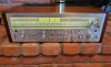
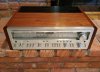
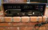
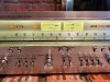
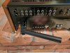
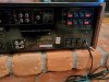
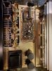
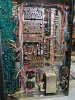
As promised, here are some pic of the completed project, starting with the outside and moving to the inside.....

2a.jpg 1a.jpg 3.jpg 4.jpg 5a.jpg
 

Attachments

  • FM strength (2).jpg
    FM strength (2).jpg
    114.2 KB · Views: 10
Last edited:
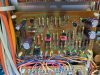
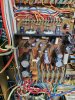
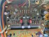
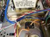
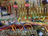
Some inside pic, including Protection board, Power Supply, EQ board (all of which got new caps and transistors), and new relay (installed into original case).

z-inside (1).jpg z-underside.jpg Protection board-new caps, trans.jpg Pwr Supply board-new caps, trans.jpg EQ board-new caps, trans.jpg new relay installed.jpg flyback diode installed.jpg
 
Back
Top Bottom