• The move to the new server is done. There are some software and database maintenance updates in process. This has us passing the hat around to help out. We appreciate any donations. Seriously, even a dollar helps. The payment page may be found here - https://www.audiokarma.org/support.html

Correcting Display Instability and Speed Issues: DT Timers

1mike161

New Member
The following instructions describe how to solve display instability (mode flicker) and clock speed accuracy problems that can occur with Pioneer DT series timers. These problems are due to failing internal resistors of the MN6076 clock chip. The solution is to add four 10K Ohm 1/8 Watt external resistors to the mode select and line frequency select inputs.

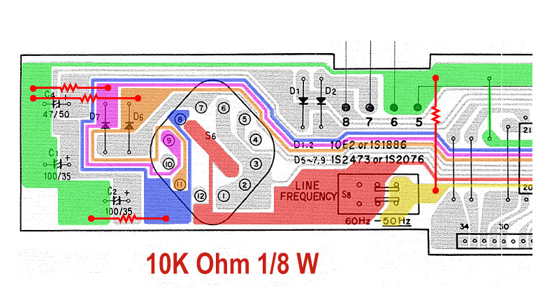
All 4 resistors have one end tied together, and then tied to pin 27 of the chip. Then, the other end of the resistors are to be tied, individually, to the following pins: 29, 30, 31, and 36. That should solve most issues with these units.

Alternatively, the 4 resistors can be installed on the PC board at locations where they can be easily mounted. The attached diagrams illustrates this method. The red trace is Vss and the green is Vdd (pin 27). The blue, purple, and orange traces are the 3 mode select inputs (pins 29, 30, & 31). The yellow trace is the line frequency select input (pin 36). The new external resistors are shown in bright red.

 
Register to hide this ad
Thanks for getting this done. I have a DT timer, part of a set and so if I have trouble with this, I'll know to come back here!
 
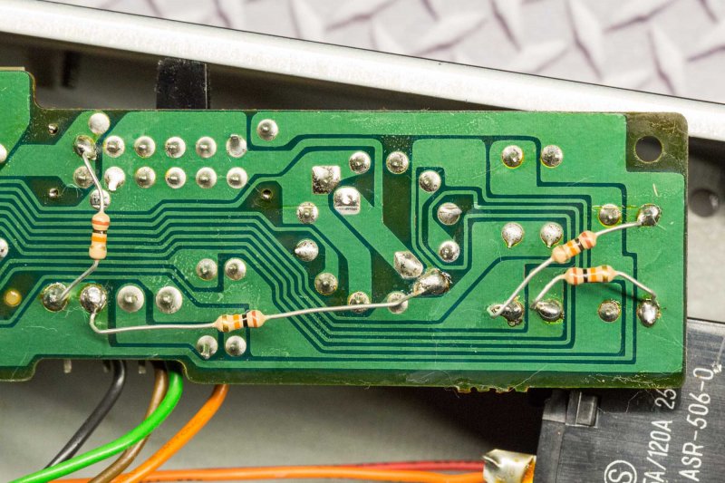
I made the modifications to my DT-510. It took me less than 2 hours. My unit had deteriorated to the point where the flickering had stopped and it it was permanently stuck on 12:00 am. I connected the resistors based on easy of installation. I didn't want to drill holes in the PC board and I was afraid to connect the resistors directly to the clock chip pins. So, I connected the resistors to existing components with long leads. And now, my DT-510 works again! Thanks @pustelniakr! I would have never figured this out on my own.

Mike


i also did those resistors but in vane plus switchs cleaned , my dt 500 still jumps hours and minutes like hell.......is there anything more i can do?...i cant even set time , if i start at 00.00 and push twice it goes to 7.06 , then after a minute is 23.09, ......
 
Last edited:
i also did those resistors but in vane plus switchs cleaned , my dt 500 still jumps hours and minutes like hell.......is there anything more i can do?...i cant even set time , if i start at 00.00 and push twice it goes to 7.06 , then after a minute is 23.09, ......
Sounds like you may have a bad clock chip. It is rare, but it happens.

Rich P
 
Thank you! Implementing the bottom configuration solved the clock instability problems. I was going to throw my DT-500 in the trash but my wife told me to try one more time! It worked!
 
Hi guys, I have the DT-555 and it is flicking, I am going to try this method to fix it but first I must fix the problem with the Voltage Selector.
The wires have been connect on the connector pins for 120v, I now have a new Selector Switch and want to put the wires back to the orginal configuration.

So, can I use the schematic for the DT-500 as a reference to resolder the wires to the selector?
Please help as I don't want to cross any of the wires, oh and I have already desoldered a few of them before double checking...oops (newbie).

Thank you for any support, Ernie
 
@1mike161: Many thanks! I recently implemented your fix on my DT-550, and so far so good - it seems to have fixed the random occurrences of it jumping to 12:00 and just staying there. I also recapped it right after I added the pull-up (pull-down?) resistors, just for good measure.
IMG_8215_crop0.JPG
 
@1mike161: Many thanks for your post. Thanks to you, I was abble to save my Timer DT-540, and now works like new!

Many thanks and greatings from Portugal.
 
The following instructions describe how to solve display instability (mode flicker) and clock speed accuracy problems that can occur with Pioneer DT series timers. These problems are due to failing internal resistors of the MN6076 clock chip. The solution is to add four 10K Ohm 1/8 Watt external resistors to the mode select and line frequency select inputs.

All 4 resistors have one end tied together, and then tied to pin 27 of the chip. Then, the other end of the resistors are to be tied, individually, to the following pins: 29, 30, 31, and 36. That should solve most issues with these units.

Alternatively, the 4 resistors can be installed on the PC board at locations where they can be easily mounted. The attached diagrams illustrates this method. The red trace is Vss and the green is Vdd (pin 27). The blue, purple, and orange traces are the 3 mode select inputs (pins 29, 30, & 31). The yellow trace is the line frequency select input (pin 36). The new external resistors are shown in bright red.

I have a DT-555 with dim display. Seems to be keeping time correctly. Would this be the fix I am seeking? Would the same results be achieved by replacing the whole MN6076 timer chip?

Bill
 
@OtownBill7: If it's just a dim display with no instability problems, then the answer in all likelihood will be 'no'.

Troubleshooting a dim display should start with ruling out power supply problems (you should confirm voltages). Also inspect for cold or cracked solder joints, and for solid interconnections. Then make sure to clean both surfaces of the plastic filter that sits in front of the VFD tube, as well as the glass surface of the VFD tube itself (I had a DT-550 which had apparently lived in a smoker's house and the display brightness benefited greatly from a thorough cleaning). Once you've ruled out those items, then the most likely cause is that your VFD is suffering from advanced age. They can be prone to dimming from extended use over time. The good news is there is a procedure which can sometimes "refresh" a VFD and restore the brightness, although it will then presumably dim again at some point in the future from continued use.

I'm not a chemist, but the general theory is that the filament wires within the VFD (vacuum fluorescent display) suffer from a loss of available barium (or thorium?) atoms with extended use, and you can refresh the VFD by "cooking" the filament to free up additional barium (or thorium?) within the filament wires. The procedure involves heating the filaments with a slightly higher DC voltage, using a 9V battery or a constant current power supply, for a brief period of time. The goal is to heat the filaments until they glow orange (but not white!) for a few seconds, and repeating that a few times. This heating produces a reduction reaction in the filament wire to make more barium available and this is what rejuvenates the brightness of the VFD.

If you search you should be able to find multiple threads that discuss this general method for rejuvenation of dim VFD's. Here's one example on AK but there are others, and here's an interesting one on eevblog.

Final disclaimer: I have not tried this myself, try this at your own risk! I am sure that overheating the filament wires, either too hot or for too long, will cause unrecoverable damage to the tube. Best of luck to you if you try it.
 
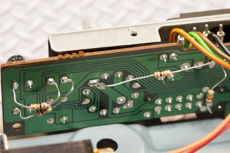
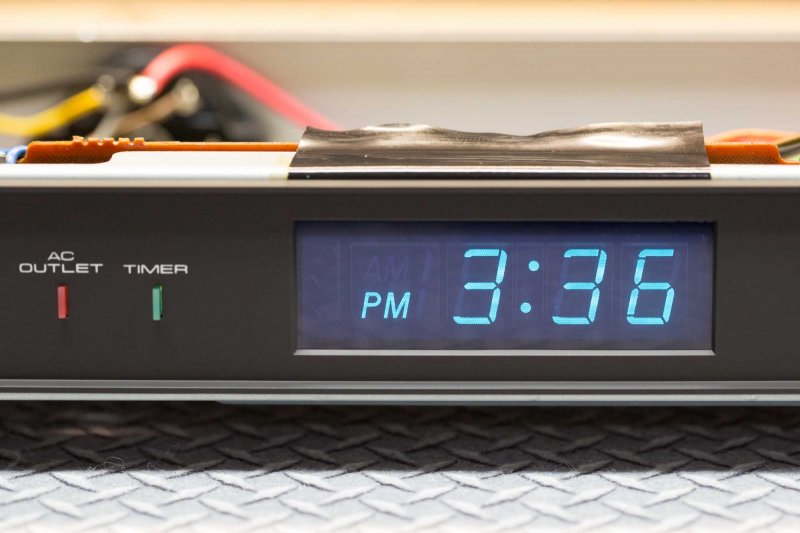
This six year old post saved my DT-500 from the closet (I rarely throw even defective equipment away)! I want to be the next person to say thank you! I was abler to add a single resister as shown to fix my flicker issue. Mine would flicker when "Clock" was selected, between the clock and the minutes/seconds. After about five seconds, it would stay on the minutes/seconds. Since the bodge, I've left the unit running for 30 minutes and it appears rock solid.

I picked this unit up at Goosdwill. After taking it apart to troubleshoot, I noticed a darkened (from heat) area in the upper right hand corner of the VFD, though I don't know if that's normal. I've confirmed the voltage going to the tube is correct. I'll keep an eye on it.

Thanks again 1Mike161, for your original post!
 

Attachments

  • DT-500-1.jpg
    DT-500-1.jpg
    128.7 KB · Views: 24
  • DT-500-2.jpg
    DT-500-2.jpg
    88.6 KB · Views: 24
This six year old post saved my DT-500 from the closet (I rarely throw even defective equipment away)! I want to be the next person to say thank you! I was abler to add a single resister as shown to fix my flicker issue. Mine would flicker when "Clock" was selected, between the clock and the minutes/seconds. After about five seconds, it would stay on the minutes/seconds. Since the bodge, I've left the unit running for 30 minutes and it appears rock solid.

I picked this unit up at Goosdwill. After taking it apart to troubleshoot, I noticed a darkened (from heat) area in the upper right hand corner of the VFD, though I don't know if that's normal. I've confirmed the voltage going to the tube is correct. I'll keep an eye on it.

Thanks again 1Mike161, for your original post!
What is the correct voltage to the tube? I have 2 of these and one is a bit dim but I can't find the voltage values coming from the transformer. I have the repair manual.
 
I just learned the hard way one cannot simply replace the chip for a new one, as it is permanently attached to the clock display, all those solder connections, ugh! On the upside: I got lots of desoldering/ soldering practice, and practice with getting all those 'legs' back into place. at least it's back together and working as it was :10 minutes fast per hour, now for the resistor fix... and 2 hrs and two trips to the hardware store ...works like a charm, down to the second! thanks Audiokarma community and Dr Strangelove aka 1mike161.
 
Last edited:
After taking it apart to troubleshoot, I noticed a darkened (from heat) area in the upper right hand corner of the VFD, though I don't know if that's normal. I've confirmed the voltage going to the tube is correct. I'll keep an eye on it.

Thanks again 1Mike161, for your original post!
have the exact same condition on mine ..doesn't seem to effect anything so....
 
Back
Top Bottom