• The move to the new server is done. There are some software and database maintenance updates in process. This has us passing the hat around to help out. We appreciate any donations. Seriously, even a dollar helps. The payment page may be found here - https://www.audiokarma.org/support.html

CR-2020 bias adjustment issue after replacing some transistors

asolochek

AK Subscriber
Subscriber
I got a CR-2020 recently that had some issues on the right channel, and I slipped while probing it and created even more issues. After all the dust settled, I'm left with a right channel that I can't get the bias voltage below 20mV. There is also more THD on the right channel than the left.

I was swapping parts between the left and right channels to try to find the source of the distortion, but wasn't able to trace it to any transistor. However I wasn't checking the bias setting while doing that. Currently, the left channel has the original TR611 and TR612, and the right has replacements, MJE15030G and MJE15031G. The right side also had TR609 and TR610 replaced with the original part numbers, but left has the originals. Both channels had TR613 replaced with MJ15003G, TR614 with MJ15004G, TR604 and 605 with 2SC2240, and I replaced the trimmers with a 25 turn bourns 50k to try to make the adjustment less fiddly. I also replaced a few out of spec resistors, and FR601 on one of the channels was blown so I replaced it with a 100mA fuse in series with a 68ohm resistor since I couldn't find a single replacement part.

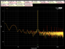
Currently the bias adjustment is my biggest concern. I could try swapping TR611/612 between channels to see if that's causing it, but even that's the cause, what is the fix? Are there better replacements for those parts than what I picked? Also does anyone have any ideas about the distortion I'm seeing in the right channel? The distortion is definitely coming from the right amp board as I've swapped both the inputs and outputs to it to verify. This output was with a 50mV signal split into both L&R main in terminals.
goose 2025-10-13 23-23-01.png

PS: even with the 25-turn pot, adjusting the bias on the left channel is super fiddly. Is that normal on these units?

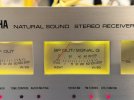
PPS: the right power/signal meter isn't zeroed. Is there a way to do that?
IMG_0086.JPG
 
Register to hide this ad
Currently, the left channel has the original TR611 and TR612, and the right has replacements, MJE15030G and MJE15031G. The right side also had TR609 and TR610 replaced with the original part numbers, but left has the originals. Both channels had TR613 replaced with MJ15003G, TR614 with MJ15004G, TR604 and 605 with 2SC2240 …
Why did you decide to change Tr611 and Tr612? Had they failed? If so, did you check them out of circuit? MJE15030G and its complimentary part aren’t the right parts, MJE180G and MJE170G would be much closer replacements:


I didn’t have time to check the other two transistor replacements. Please refrain from replacing parts as a way of solving the problem, it will only add more problems. Also, generally I’d leave resistors alone, unlike capacitors, they do not drift off over time unless abused or something done to them. Most have ±20% tolerance window which is different from drifting.

Try isolating where the instability comes in, your photo looks like a transistor flying (oscillating) somewhere.
 
The distortion is definitely coming from the right amp board
Did you confirm with a separate pre-amp or power amp? Distortion could be just a dirty coupler switch on the rear panel. They are notorious for getting filthy.
 
Why did you decide to change Tr611 and Tr612? Had they failed? If so, did you check them out of circuit? MJE15030G and its complimentary part aren’t the right parts, MJE180G and MJE170G would be much closer replacements:


I didn’t have time to check the other two transistor replacements. Please refrain from replacing parts as a way of solving the problem, it will only add more problems. Also, generally I’d leave resistors alone, unlike capacitors, they do not drift off over time unless abused or something done to them. Most have ±20% tolerance window which is different from drifting.

Try isolating where the instability comes in, your photo looks like a transistor flying (oscillating) somewhere.
Yeah, TR 611 and 612 blew (along with some other things). I do have supposedly NOS of the originals on the way, but I'll get your suggested replacements just in case I get sent fakes.
 
Did you confirm with a separate pre-amp or power amp? Distortion could be just a dirty coupler switch on the rear panel. They are notorious for getting filthy.
I literally swapped the soldered input and output wires between the two boards to definitively isolate the problem.
 
Why did you decide to change Tr611 and Tr612? Had they failed? If so, did you check them out of circuit? MJE15030G and its complimentary part aren’t the right parts, MJE180G and MJE170G would be much closer replacements:


I didn’t have time to check the other two transistor replacements. Please refrain from replacing parts as a way of solving the problem, it will only add more problems. Also, generally I’d leave resistors alone, unlike capacitors, they do not drift off over time unless abused or something done to them. Most have ±20% tolerance window which is different from drifting.

Try isolating where the instability comes in, your photo looks like a transistor flying (oscillating) somewhere.
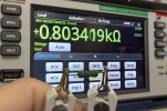
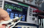
So I think the avalanche failure that took out a bunch of the transistors came from me probing voltages. I have noticed the circuit is quite reactive to even the very high impedance of my multimeter. Attempting to measure some of the voltages caused the receiver to go from drawing about 40 watts to over 100 watts.

I have an amplifier that will let me use a 10x scope probe on my spectrum analyzer, but I've been afraid to try it on this board.

As for the resistors, I replaced R627 and R628 because they were way out of spec, and R630 because it looked scortched (although was still dead on 470 ohms)
 

Attachments

  • IMG_0090.jpeg
    IMG_0090.jpeg
    103.5 KB · Views: 8
  • IMG_0092.jpeg
    IMG_0092.jpeg
    108.3 KB · Views: 8
How do you know that is a suitable replacement? The schematic specifies only 68 ohms 100mA, which would be .68W, so a 1W resistor is nearly twice the power rating. Also, that resistor is a flameproof safety resistor, but does safety imply fusible? Either way, I'm pretty comfortable that my solution of these two parts in series meets the specifications.

 
Why did you decide to change Tr611 and Tr612? Had they failed? If so, did you check them out of circuit? MJE15030G and its complimentary part aren’t the right parts, MJE180G and MJE170G would be much closer replacements:


I didn’t have time to check the other two transistor replacements. Please refrain from replacing parts as a way of solving the problem, it will only add more problems. Also, generally I’d leave resistors alone, unlike capacitors, they do not drift off over time unless abused or something done to them. Most have ±20% tolerance window which is different from drifting.

Try isolating where the instability comes in, your photo looks like a transistor flying (oscillating) somewhere.
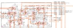
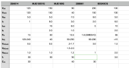
I was looking at the MJE180G/MJE170G and they have a maximum collector-emitter voltage of 40V. The schematics I have show 59.1V on the collector and 0.69V on the emitter, so I don't think those will work. I threw together this spreadsheet of a couple of suggested replacements I've seen, and the MJE15031G looks like a good replacement apart from the lower gain.
 

Attachments

  • Yamaha CR-2020 Service Manual .pdf 2025-10-14 11-25-20.jpg
    Yamaha CR-2020 Service Manual .pdf 2025-10-14 11-25-20.jpg
    80.4 KB · Views: 9
  • Untitled.numbers 2025-10-14 11-13-31.png
    Untitled.numbers 2025-10-14 11-13-31.png
    71.7 KB · Views: 9
I was looking at the MJE180G/MJE170G and they have a maximum collector-emitter voltage of 40V. The schematics I have show 59.1V on the collector and 0.69V on the emitter, so I don't think those will work. I threw together this spreadsheet of a couple of suggested replacements I've seen, and the MJE15031G looks like a good replacement apart from the lower gain.
KSC2073 and a KSA940 is what I would use.


Ordered them soon as they are end of life and a few thousand came in about a week ago and already they are almost gone.

Athanasios
 
Suggest recheck the suitability of these, one appears to be a 2W wirewound the other is not 68ohm 100mA
I just rechecked them and the 100mA fuse has a nominal resistance of 7.49ohms, so putting that in series with the 68ohm does make it a little high. Conveniently there are also 60.4ohm 1W safety resistors that will bring the combination back to 68ohms.
 
I just rechecked them and the 100mA fuse has a nominal resistance of 7.49ohms, so putting that in series with the 68ohm does make it a little high. Conveniently there are also 60.4ohm 1W safety resistors that will bring the combination back to 68ohms.
Just use ohms law and get that rated wattage value resistor at 68 ohms that is flame proof. That's all you need and basically what the old part was. .
 
Just use ohms law and get that rated wattage value resistor at 68 ohms that is flame proof. That's all you need and basically what the old part was. .
Well that comes out to .68W. Digikey has .6W, and mouser has .65W, but neither of them are flameproof.
 
100mA fuse has a nominal resistance of 7.49ohms
Keep in mind that it's a fast acting fuse, the OEM FR's can take a bit of a hammering and drift high, my concern would be that the fast acting fuse would be forever "tripping"
 
Keep in mind that it's a fast acting fuse, the OEM FR's can take a bit of a hammering and drift high, my concern would be that the fast acting fuse would be forever "tripping"
Yeah, I'm a little concerned about that too. I suppose if it happens I can always put the 1W fusible in place. The downstream transistors may end up being able to handle the higher power anyway, depending on which replacements I land on.
 
I was looking at the MJE180G/MJE170G and they have a maximum collector-emitter voltage of 40V. The schematics I have show 59.1V on the collector and 0.69V on the emitter, so I don't think those will work. I threw together this spreadsheet of a couple of suggested replacements I've seen, and the MJE15031G looks like a good replacement apart from the lower gain.
Sorry, copied the wrong links, here are the ones I meant to post:

Lesson: Don’t copy and paste while changing trains …
 
So I think the avalanche failure that took out a bunch of the transistors came from me probing voltages.
This is abnormal, there’s something else wrong here. Any chance you use a different DMM? Is everything grounded properly? Sometimes having the amp in pieces, meaning inside components removed/loose, can cause this kind of thing although even that’s kind of rare. Or maybe your mishap affected other parts you’re not aware of.
 
Back
Top Bottom