• The move to the new server is done. There are some software and database maintenance updates in process. This has us passing the hat around to help out. We appreciate any donations. Seriously, even a dollar helps. The payment page may be found here - https://www.audiokarma.org/support.html

Cr-2020 Troubleshooting

Mike1767

New Member
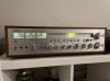
I have recently brought home a 2020 from my parent's basement that I am hoping to bring back to life. Growing up, it was my Dad's pride and joy, but it has now been sitting unused for too long. I am half decent with a soldering iron and multimeter and can read a circuit diagram, but I can't troubleshoot my way out a paper bag.

Here's what I know. The unit powers up, lights all lamps, FM tuner meter swings halfway left then doesn't move and the relay never clicks on, so no audio. The service bulletins were all done a number of years ago. I replaced a half dozen caps on the power supply board that had shrunken wrappers to no effect.

After reading a number of threads and seeing the common asks for measurements, I made the attached image with the readings that I've taken. Hopefully it's legible on here, it is at full size. In addition to what's on the image, I get +/- 61 VDC at the output transistors and the idle current measures right around 10mV.

There are a couple of obvious (I think at least) issues in the measurements I've taken. The biggest standouts are emitter on TR714 being in the millivolts, the base of 715 being +8.6 VDC and the -25 post reading +8.7. My problem is knowing the source of any of these issues. Any help you could provide would be great. Thanks!
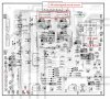
Power%20Supply%20Board-page-001.jpg
 
Register to hide this ad
Thanks. Those are from the outer casings (collectors I think?) of the power transistors (again, I think. It's TR613 and 614). I likely misunderstood the directions you gave in a really old thread (Measure the collector voltage on the output transistors (the metal outer casing is the collector on a TO-3 transistor.) Should be roughly + and - 49vdc. rail voltage.)
I'm headed to bed soon, but I'll certainly follow up on any replies tomorrow. Thanks for the initial reply.
 
I had those approximate voltages on the on the regulator pass transistors on my CR2020 after rebuilding the power supply board and my unit would similarly not come out of protection, despite working before the rebuild.

it turned out to be hairline fractures of the PCB traces that connect to these transistors.

the problem seemed to have arisen as the transistors and heat sinks are only supported by these pcb pads and the movement caused by moving the board about during work seem to flex them back and forth, causing them to break.

I discovered the breaks when I desoldered the pass transistors with a solder sucker.

Might worth a quick look.
 
it turned out to be hairline fractures of the PCB traces that connect to these transistors.
Thanks Bob. I took a look and reflowed the joints on 714 and 715. Unfortunately I'm still getting the same numbers. Any idea what I should be looking for, voltage wise, at the emitter of 714?
 
Certainly don't open up your unit just for that, but if you have it open on a bench, then that would be appreciated. I think that I should be able to find the voltages on a schematic, but I can't find one that is legible enough for me to make them out.
 
When my 2020 wouldn't come out of protection mode - post recapping the main capacitor printed circuit board (pcb), and the relay pcb, I discovered that some of the capacitor and resistor connections on the main cap. board had become 'disconnected'.
Because of the heat in that area, I needed to actually fabricate some of the connections from strands of braided copper wire,and reconnect some of the soldered components. Definitely worth taking a look at.
 
Thanks Bob. I took a look and reflowed the joints on 714 and 715. Unfortunately I'm still getting the same numbers. Any idea what I should be looking for, voltage wise, at the emitter of 714?
No trouble at all, I have one open on my bench that works perfectly apart from my weird clipping issue, as detailed in the thread "mid restoration regrets" which is also about a CR-2020 and how much of an unrelenting bastard they are work.

Worth it though as they do look and sound rather tasty when all fixed up.
 
When my 2020 wouldn't come out of protection mode - post recapping the main capacitor printed circuit board (pcb), and the relay pcb, I discovered that some of the capacitor and resistor connections on the main cap. board had become 'disconnected'.
Because of the heat in that area, I needed to actually fabricate some of the connections from strands of braided copper wire,and reconnect some of the soldered components. Definitely worth taking a look at.
This also happened on my board, I relocated the power resistors to the back side of the PCB and must have knocked them getting the transformer back in place.
 
When my 2020 wouldn't come out of protection mode - post recapping the main capacitor printed circuit board (pcb), and the relay pcb, I discovered that some of the capacitor and resistor connections on the main cap. board had become 'disconnected'.
Because of the heat in that area, I needed to actually fabricate some of the connections from strands of braided copper wire,and reconnect some of the soldered components. Definitely worth taking a look at.

Thanks for the reply. Is there a good way to test for this? Is it just visual inspection, or can I be testing for continuity between components?
 
When I was poking around testing components for continuity I noticed that the base and collector of TR715 show continuity. I figured I did a crap job with some solder there, so checked the underside of the board and it looked okay. While doing that I noticed that they aren't shorted when the board is unplugged from the 6 pin connector. Seemed odd to me, but I'm learning as I go, so maybe not? Is that normal behaviour or a clue as to what might be going on?
 
This also happened on my board, I relocated the power resistors to the back side of the PCB and must have knocked them getting the transformer back in place.
When my 2020 wouldn't come out of protection mode - post recapping the main capacitor printed circuit board (pcb), and the relay pcb, I discovered that some of the capacitor and resistor connections on the main cap. board had become 'disconnected'.
Because of the heat in that area, I needed to actually fabricate some of the connections from strands of braided copper wire,and reconnect some of the soldered components. Definitely worth taking a look at.
The short trace between the collector of TR715 and the emitter of TR714 wasn't complete. I added some braided copper to bridge the connection and, sure enough, the relay now clicks on. Thanks for the suggestions! The voltage readings now all appear pretty close to those on the schematic.

Now, the problem is back to what it was a ways back (when my dad originally shelved it), which is that it will still intermittently cut out. It seems surprisingly random. Sometimes within minutes of powering up, other times it will play for an hour without issue. The one consistency is that there's a slight popping then the audio cuts, the FM tuner sweeps and holds half left and the voltage on the -25 peg jumps to +8. Any ideas if this is likely an issue with my recent "fix" or something else altogether? Is a full recap of the electrolytic cap board and the power supply board likely to help? I have a capacitor tester coming today, so I may start pulling and testing caps if a dying capacitor could be the root cause of the issue.

Anyway, thanks again for the help.
 
I did a full recap of the capacitor board and power supply/relay board, and it eliminated the intermittent popping that I had been getting originally.
I understand that the 2 large caps. (18k µf) on the main cap.pcb do not usually go bad. I DID replace mine, but the new ones I used took-up less space than the originals. So I had to compensate for difference in size, so the new large caps wouldn't rattle themselves loose, and unsolder themselves. If possible - use the old/original 18k µf caps. just for that reason. It'll save you from having to configure a new supporting/securing arrangement for their replacements.
 
Also, when replacing the capacitors - do them one-at-a-time - taking care to make sure the polarity does not get reversed.
I found that the de-soldering braid works the best. Don't waste your time/money on solder-suckers. I did not have much luck (if any) with those. Make sure you have a good soldering iron, and some good flux as well. An old toothbrush and rubbing alcohol can help a lot with any clean-up too.
 
Also, when replacing the capacitors - do them one-at-a-time - taking care to make sure the polarity does not get reversed.
I found that the de-soldering braid works the best. Don't waste your time/money on solder-suckers. I did not have much luck (if any) with those. Make sure you have a good soldering iron, and some good flux as well. An old toothbrush and rubbing alcohol can help a lot with any clean-up too.
One at a time is probably good advice, I could see myself making a dumb mistake otherwise. I should be good on the rest. I've got some decent equipment for some arduino projects from my past life as a teacher.

I understand that the 2 large caps. (18k µf) on the main cap.pcb do not usually go bad.
Yeah, I'm certainly hoping to stay away from those 2.
 
Just wanted to come back and give a conclusion in case anyone ever reads this and is having similar issues.

I started by doing a full recap of the power supply (relay) and electrolytic capacitor boards (minus the 2 big filter caps). The only caps that measured out of spec were the 3 on the electro. cap board right above the big guys. Unfortunately, that didn't solve the issue. Next up I decided to replace the 4 resistors from the SB. The work had been done professionally a number of years ago, but they applied way too much heat and the had to create a few new traces. It took a good bit of patience to clean up all of the old solder and remove the resistors, but I got there without any more damage to the board. I reinstalled new resistors and made traces where needed. While I was right there, I cleaned up and reflowed the solder around the 6 pin connector. Somewhere in there was the problem, because the unit is back up and running without issues again! If I had to guess what it was exactly, I would say that the there was most likely an issue in the trace between FR802 and the NB- pins. That fits with me having issues with the voltages at TR714 and it's where there was evidence of too much heat on the board.

Thanks for the help along the way.
 

Attachments

  • IMG_0292.jpg
    IMG_0292.jpg
    65.5 KB · Views: 10
Back
Top Bottom