• The move to the new server is done. There are some software and database maintenance updates in process. This has us passing the hat around to help out. We appreciate any donations. Seriously, even a dollar helps. The payment page may be found here - https://www.audiokarma.org/support.html

CR-800 Pre-Amp Issues?

bkouba

Member
I recently acquired the unit with unknown functionality. After doing some testing I was able to fire it up, but it had no sound from any input.

I have a relay click on power on, lights work, and was actually able to go through and set bias and offset. I cleaned the controls and coupler switch in the back but still no sound. I finally did a test of the main amp by turning the coupler off and connecting to Main In--was able to get sound through the speakers this way. So, I'm thinking something on the pre-amp is preventing any signal from getting through. Nothing appears bad/burned, solder connections appear okay, etc.

My question is where should I even begin on that board? Is it just a systematic check of all components or does someone have some tips of notorious culprits? Am I even headed in the right direction?

Any suggestions are greatly appreciated. Thank you and Happy New Year!
 
Register to hide this ad
Welcome to AK

First I'd check switch settings. Like speaker select,mute and Tape. Have you tried any other sources?
 
Is it just a systematic check of all components or does someone have some tips of notorious culprits? Am I even headed in the right direction?
Need to verify power supply voltages to the EQ amplifiers If all the switches are properly selected.
 
Need to verify power supply voltages to the EQ amplifiers If all the switches are properly selected.

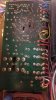
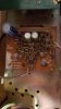
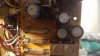
To the EQ Amp I measure ~24mV DC coming off the power board. However when I measure on the EQ board I only get 5mV DC. This is via the yellow wire (+BE). See the pictures attached (supply wire on power board is the yellow wire in the bottom right...). My board is a little different the SM I have.
 

Attachments

  • 20191231_175020.jpg
    20191231_175020.jpg
    47.2 KB · Views: 13
  • 20191231_175027.jpg
    20191231_175027.jpg
    37.7 KB · Views: 12
Last edited:
It does look like the SM, yes. I had traced the wire incorrectly before anyway.

I get 18mV AC from BT point on power board and about 10mV DC from BE. I did check all transistors on power board 801-807 and they all check out good.

Had to repair a couple traces so am waiting for it dry before I resolder. Won't be able to measure at the pre amp board for a bit. I assume it's the thin yellow wire that connect to the power board via the lamps on the meter? At least I think that's how it connects when I tried following it.
 
The little EQ board later...

PRE- amp board is the prime suspect.
 
Look at fusible resistor FR801 (47Ω 1/2 watt) In the power supply.Check its resistance. Check the solder connections on TR802 while your in the neighborhood.

This is the power supply for the +BE voltage. Its key to both the PRE and EQ boards.
 
I will have to remeasure for you. I screwed up the first time around and had my points incorrect. Though, the BT/BE voltages above don't sound right either. 18mV AC from BT point on power board and about 10mV DC from BE

I did notice earlier that the relay clicked a couple times when I had it on. Didn't do it the last time I was checking so I hope other things aren't starting to go too.
 
I will have to remeasure for you. I screwed up the first time around and had my points incorrect. Though, the BT/BE voltages above don't sound right either. 18mV AC from BT point on power board and about 10mV DC from BE

I did notice earlier that the relay clicked a couple times when I had it on. Didn't do it the last time I was checking so I hope other things aren't starting to go too.
Check the solder connections on all the TO-220 transistors in the entire power supply.
 
fusible resistor FR801 (47Ω 1/2 watt)

FR801 is OL! Doesn't look it. I'll make sure to go check the others too to be safe.

Stupid question...if it's a fusible resistor where is the best source to get them since they aren't normal resistors? Mouser, Digi-key, etc?
 
I had those off yesterday to check them so will make sure I didn't bugger any. All tested good...then.
OK .. So the solder connections should all be new.I was looking for possible cracked solder connections. But seeings how the transistors tested good and the fusible resistor is "open". Maybe just a fusible replacement will remedy the problem.
 
index.php
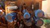
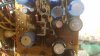
The two black ones in the center of the photo look like the plastic has shrunken a bit.
 
Back
Top Bottom