• The move to the new server is done. There are some software and database maintenance updates in process. This has us passing the hat around to help out. We appreciate any donations. Seriously, even a dollar helps. The payment page may be found here - https://www.audiokarma.org/support.html

Crackle and pop on a SX-525 with DIY speaker plugs

Pioneer SX-525 FW Transistors

Here are the transistors listed in the service manual for the Power Supply and Control amp, and the suitable replacements available from mouser (and verified elsewhere on these forums)..

Pioneer SX-525, version FW

Power Supply
AWR-007 Q1- 2SD313- E or D ----> 512-KSC2073TU

Control Amp
AWG-001 Q1- 2SC1000- GR or BL ----> 512-KSC1815YTA
AWG-001 Q2- 2SC1000- GR or BL ----> 512-KSC1815YTA
 
HEAD AMP
AWF-003 Q1/Q2 2sc871 E or F-----> KSC1845FTA
AWF-003 Q3/Q4 2sc870 E or F-----> KSC1845FTA

This leaves the MAIN AMP predrivers and drivers.
 
awr-065 awr-067

q1 2sd234 50v 3a
512-KSD526Y npn to-220 bce 80v 4a 30w 3mhz 15-240hfe

q2 2sc945
512-KSC2383YBU to-92L ecb 160v 1a .9w 50mhz 160-320hfe

q3 2sd313 60v 3a 30w 5mhz
512-KSD526Y npn to-220 bce 80v 4a 30w 3mhz 15-240hfe
512-ksc2073 will be ok, there's not that much current draw.


d1-4 hs-3
d5-7 1s1886
512-1n4004 conventional rectifier 1a 400v $0.06 ea

d8 wz-140
512-1N5244B Fairchild 14 V, 0.5W Zener


awh-035

q1-4 2sa726 or 2sa763
512-KSA992FBU (ln)to-92 ecb 120v .05a .5w 100mhz 150-800hfe $0.05 ea

q5-8 2sc1318
512-KSC2383YBU to-92L ecb 160v 1a .9w 50mhz 160-320hfe $0.17
q9,q10 2sa720
512-KSA1013YBU to-92L ecb 160v 1a .9w 50mhz 160-320hfe $0.17 (R=60-120, O=100/200, Y=160/320)

to-220
q11,12 2sc789 npn to-220 bce 70v 4a 30w 3mhz
512-KSD526Y npn to-220 bce 80v 4a 30w 3mhz 15-240hfe $0.62
512-tip41C/a/b/c npn to-220 bce 40/60/80/100v 6a 65w 3mhz 10-50hfe


q13,14 2sa489 pnp to-220 bce 70v 4a 30w 3mhz
512-KSB596Y pnp to-220 bce 80v 4a 30w 3mhz 15-240hfe $0.62
512-tip42C/a/b/c pnp to-220 bce 40/60/80/100v 6a 65w 3mhz 10-50hfe

There are a lot of tip-41,42 suppliers including Fairchild and OnSemi, get the C version for the voltage rating.
 
Last edited:
Pioneer SX-525 FW Transistors

Thanks Mark and Larry

Mark, those look to be the transistors for a 535, though some of the assignments are the same, so the transcriptions are helpful - here is a complete..

PRELIMINARY LIST of transistor replacements on my SX-525, version FW

Power Supply AWR-007
Q1- 2SD313- E or D ----> 512-KSC2073TU
D1,D2 - FR2-02 ----> 512-1N4004
D3-D5 - SIBO1-02 ----> 512-1N4004 (?)
D6 - WZ-320 ----> 512-1N5257B

Head Amp AWF-003
Q1/Q2 2sc871 E or F-----> KSC1845FTA
Q3/Q4 2sc870 E or F-----> KSC1845FTA

Control Amp AWG-011
Q1,Q2- 2SC1000- GR or BL ----> 512-KSC1815YTA

Main Amp AWH-006
Q1-Q4 - 2SA572- 4B, 5A, or 5B ----> 512-KSA992FBU
Q5-Q8 - 2SC1318- R or Q ----> 512-KSC2383YBU
Q9,Q10 - 2SA720- R or S ----> 512-KSA1013YBU
Q11,Q12 - 2SC789-O ----> 512-KSD526Y
Q13,Q14 - 2SA489-O ----> 512-KSB596Y
Q15,Q16 - 2SC1318 R or S ----> 512-KSC2383YBU

D1,D2 - 1S2O76 ----> leaving alone
D3,D4 - SV-4A ----> leaving alone
D5 - 1S2076 ----> leaving alone
D6 - SIBO1-02 ----> 512-1N4004 (?)


Larry - in your reply regarding the capacitors you stated an order of operations (with tests in between each step)
Power Supply > Head amp > Control Amp > Main amp board
- does that hold the same for transistor replacement?
 
Last edited:
Yeah. I do both caps and transistors at the same time when needed. Why work on a board twice. But in your case is may be better to work the transistors on the power supply then work backwards from the amp to the head amp. Make sure the supply voltages are good 1st then everthing else will fall into line.
 
Yeah. I do both caps and transistors at the same time when needed. Why work on a board twice. But in your case is may be better to work the transistors on the power supply then work backwards from the amp to the head amp. Make sure the supply voltages are good 1st then everthing else will fall into line.

As we're working through making these lists, I opened up the receiver last night, and poked at the power supply transistor with a dowel - I pushed it slightly, it bent a bit, and the sound cleared up a bit, even in the nasty left channel - pretty hopeful thats where its at!
 
check the solder joints on the bottom of the board if you can see/access it easily, they tend to crack after years of heating and cooling.

It IS always better to fix faults first, then spiff things up. Sometimes the "work on boards twice" thing comes into play though, and it all gets done at once.
 
It's been quite the chore desoldering this board - I'm using the bulb but may get the braid at radio shack tomorrow. The hole will clear, but small amount of solder holds the bent wires to the board so it's very difficult to remove components.

I was able to swap the transistor on the power supply and two on the main amp- I check the sound between each replacement with headphones. So far the fuzz is still there in the right, but the left has now gone quiet (no sound). When I shut it off, only then do I hear both channels for a moment as the unit powers down.

Assuming this is due to the fact that I've not yet completed all the replacements? Could also be a bad joint which I will check tomorrow.
 
Last edited:
when desoldering, before the solder cools and the joint hardens - WIGGLE the component - that prevents the solder bridge from forming. do it all the time.

check after doing a board completely (or a group of components like capacitors then transistors, but not component by component), and be SURE nothing's missing when powering up.
 
Thanks for the wiggle tip - thats working out well!

So far I've replaced the transistor on the power amp: no change
Q1- 2SD313- E or D ----> 512-KSC2073TU

Then I replaced the transistors on the Main Amp like so, and I get nothing in the headphones - dead silence
Q1-Q4 - 2SA572- 4B, 5A, or 5B ----> 512-KSA992FBU
Q5, Q6 - 2SC1318- R or Q ----> 512-KSC2383YTA
Q9,Q10 - 2SA720- R or S ----> 512-KSA1013YBU
Q11,Q12 - 2SC789-O ----> 512-KSD526Y
Q13,Q14 - 2SA489-O ----> TIP42C
Q15,Q16 - 2SC1318 R or S ----> 512-KSC2383YTA

Because i tested it midway (as i reported yesterday) I know that the there was not dead silence after replacing Q1-Q4. I could use some direction in how to troubleshoot at this point. A million thanks for the help thus far.
 
Last edited:
take a fresh look at how the transistor's leads were arranged, using the datasheet for how the new transistors are arranged, and the markings on the PC board to determine the board's requirements for that position.
 
Ok- double and triple checked all the transistor arrangements, and they are all lined up proper. The correct replacements are all in their respective spots.

I replaced all the transistors on the main amp, didn't touch the diodes. I check all the soldering joints and they seem to be OK.

When I power the unit on, I can just hear it 'power up' in the headphones, then silence.
 
on a dim bulb tester? AND checked your front panel switch positions? (like a tape position on)

main amp and power supply worked on, right?

on the main amp, touch pins 1 and then pin 2 with your finger to inject hum.

measure the voltage found at main amp board pin 9 to ground, then the same for pin 10.

measure the +50 v at pins 5 & 6 (to ground) and see if pins 9 and 10 are half that.

check the idle current readings voltage between pins 16(red dmm) and 14(black dmm), and then the same for pins 13 and 15. 0.030v or 30mV target, adjusted by the trimpots on the board.

startup pops are supposed to be suppressed by Q15, Q16, controlled by the pin 18 8vac input. Might be suppressing almost everything... fuse can kill 8vac from the lights...

also check that the power supply is putting out +25vdc (referenced to chassis ground) on the "B2" pin.

check ALL FOUR fuses out of circuit with an ohmmeter.

posterity, gallery: this is an output capacitor unit with NO center point voltage adjustments.
 
Last edited:
OK- no hum when touching pins 1 and 2

Pins 9 and 10 reading around 53.5
Pins 5 and 6 reading around 55.7

No idle current at 16-14 or 13-15

There are no startup pops, it's more of a "current" hum when the unit is powered on, and it fades after a few brief seconds.

Power supply is putting out 25.5
 
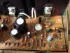
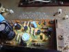
post a picture of the amp board, IIAC I remember you said everything was ok until you did the q1-q4 diffs.

concentrate on a clear view of those transistors and the board they are mounted on, use 2 pictures if necessary.

pins 9 and 10 should be half of the voltage found on pins 5 and 6. The power amp channels are "railed".

Just repeating this "just in case":
using the old transistor orientation to determine the replacement orientation is a no no :nono:
the symbol on the board shows what way the amp wants them hooked up,
and the datasheet shows what you have. 5 ways are wrong, one is correct.

and sometimes the manual is all goofed up as to a lead's identity on the drawing of the transistor.

IF the board isn't marked with a symbol, then we have to use an ohmmeter to see which components are connected to each transistor mounting pad, to tell which lead goes where.
USUALLY the marking on the board is correct, and the manual loopy, but these are early pioneers when they were still getting their $#!^ together...
 
Sure thing - I went over the arrangement so many times I'm starting to doubt it myself. If its wrong, then I have all the PNPs backward
 

Attachments

  • IMG_3707.jpg
    IMG_3707.jpg
    104.3 KB · Views: 45
  • IMG_3709.jpg
    IMG_3709.jpg
    106.9 KB · Views: 35
  • IMG_3718.jpg
    IMG_3718.jpg
    94.1 KB · Views: 31
OK, we gotta get "down" here.

First there's this post: http://www.audiokarma.org/forums/showthread.php?p=7023174&highlight=rotate#post7023174 read it carefully.

Then there's this post: http://www.audiokarma.org/forums/showthread.php?p=6816418&highlight=rotate#post6816418
which has some VERY relevant pictures as well as a restating of the installation "mental rotation".

Now, if the transistors were incorrectly installed, they could be damaged, (not just them, but their neighbors as well :tears:) so either just go with new ones in those positions, or try the 6-way EchoWars diode test as found in EchoWars's Bipolar transistor thread: Bipolar Junction Transistor Testing Basics and go to post #11 for a exhaustively specific procedure WITH correct sample results.

What you can do, would be to remove the four transistors, and photograph the board straight down so the symbols would be more recognizable, and then I will do like the bottom photograph in this post, and email it back to you (PM me an email to do that) as my list of attachments is cumbersomely large.

attachment.php


attachment.php
 
Last edited:
Ok, unhh, I've gone over this several times, blew up a section of the manual, reversed it in paint to be absolutely sure and then blew up and rechecked the photos:

q2 by pins 4 and 8

emitter is plugged into base
collector is plugged into collector
base is plugged into emitter
-------------------------------------

q4 between pins 2 and 12

base is plugged into emitter
emitter is plugged into base
collector is plugged into collector

----------------------------------------------
q3 between pins 1 and 11

emitter is plugged into base
base is plugged into emitter
collector is plugged into collector
----------------------------------------------
q1 by pins 7 and 3

emitter is plugged into base
base is plugged into emitter
collector is plugged into collector

basically it looks like q1 to q4 were installed in reverse

If its wrong, then I have all the PNPs backward
By George, I think you've got it....

I DON'T think that in those circuit positions that the a992's will survive a base-emitter reversal. But the fault will be highly visible to the 6-way diode test. (blooie..)

I am NOT going to go further with the rest of the transistors, I could but I hope that replacing q1 through q4 together with the posts I did above will be enough of a learning experience that you will be able to go back quietly and check all the remaining transistors.

ALERT:
These are OLD electrolytic caps, I had assumed you had put in the replacement caps first. I am particularly worried about the sky blue Sanyo caps with the 1/25 marked on them. They fail. period. short circuit. turn into resistors.... .GET..THEM..OUT. !!!!
 
Last edited:
I spun those transistors around proper, and now have reading like so:

yes, hum when touching pins 1 and 2

Pins 5, 9 and 10 reading around 25v-26v
Pin 6 reading around 55v-56v

I did not put in any new caps, i was trying to replace transistors first to fix the crackle. After replacing all transistors in the power supply and main amp, still have the crackle.

C1 and C2 caps are 'CSSA 010X 25' in the manual - those should be replaced with a 1uf 25v electrolytic, yes?

I will diagnose the health on those transistors tomorrow, thanks for the leads!
 
Back
Top Bottom