• The move to the new server is done. There are some software and database maintenance updates in process. This has us passing the hat around to help out. We appreciate any donations. Seriously, even a dollar helps. The payment page may be found here - https://www.audiokarma.org/support.html

Crackle and pop on a SX-525 with DIY speaker plugs

actually getting hum when you touched pins 1 and 2 PROVES the transistors in the amps are good :D
So transistors in the amp don't need to be tested.

CONGRATS.. You were lucky the a992's survived...

the caps can be contributing to the crackle - especially those Sanyo caps.

this is a hard unit to isolate the source of the crackle initially, because there are no preamp out / amp in jumpers in the back to separate the control amp from the power amp.

correct. 1uf 25v - didn't you get the caps when you ordered from mouser?

edit DRAT, no SX-525 cap list in Marty's post,

OK, you gotta make one:
do like we did for the transistors, separated by board and by component numbers, you are listing all the "electrolytic" caps which are cea and cssa caps

an example, to "prime the pump":
awg-011 control amp

awg-011 C1 3.3uf 16v cssa 3r3m 16
awg-011 C2 3.3uf 16v cssa 3r3m 16
awg-011 C7 0.47uf 25v cssa 4r7m 25
awg-011 C8 0.47uf 25v cssa 4r7m 25
awg-011 c9 3.3uf 25v cea 3r3p 25
awg-011 c10 3.3uf 25v cea 3r3p 25

and so forth
then we/I will come up with mouser numbers, as I examine the list with schematic and calculator in hand.
 
very cool, will do.

Are those voltage readings ok on the pins? I found it curious that I'm getting 50v on 6 but not 5 (25v)? :scratch2:
 
I would carefully recheck those 4 readings, because if pin 5 really has 25v on it, pin 9 should only have 12.5 volts.

If there is, look at the fuses on the back panel - each channel of the power amp has it's own 1.5 amp fuse. pull each fuse and measure it's resistance.
 
The readings were the same after a restest,

and yes sir, Left side fuse is shot. Might be able to snag one today and replace it.
 
Sparks fly on 38th street

The manual lists the protection fuses as a 1.5A 250 volt, and when I pulled the fuses that were in the unit already, they are labeled 3 1/2A 250v.


Now, I got the unit second hand, and I have no idea about any repairs or replacements that may have been made to it over the years- will the 1.5 be ok? Why would those 3.5s be in there?
 
Last edited:
use the called for 1.5's, head up arse syndrome...

at 50v x 1.5a = 75 watts conceivably, and at 1.5a the power supply should be already crapping out. 3.5a just means greater damage before it pops at 175w

maybe they were managing to pop the 1.5's...

new transistors = not any more....
 
same situation for the AC Lines fuse - now i'm not sure what the proper replacement should be there, its got a voltage selector on 110 - Schematic says a 2A fuse - match the voltage to 110? 2A 110v fuse
 
manual shows a 1 amp fuse for the switched line voltage unit

and a 2 amp fuse for the 120v exclusive model.

a 2 amp fuse if powered at 240v would be 480 watts before it pops,

go for the 1 amp fuse - you shouldn't be pulling 120 watts, not even half that, even at 120v.
 
After running Mark's suggested gauntlet of tests in post #33 - I've arrived at the following:

Main amp transistors Q5, Q7, Q9, Q11, are no longer good.

The fuses that were in the unit when i got it were all 3.5 amp, inadequate to protect the receiver.

Having the wrong fuses in place, it's probably been slow roasting the amp transistors over time.

So I need to replace those transistors this week, and try to figure out if anything is causing overload. Perhaps the prior owner had a lot of blown fuses, and took that route to remedy rather than find the source of the overloads..

_

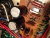
Attaching two photos of the power supply here - i'm a little concerned with that clear goo between the capacitors - is that a leak? :drool: I have to say the caps on this thing look to be in pretty good shape overall.
 

Attachments

  • IMG_3745.jpg
    IMG_3745.jpg
    96.1 KB · Views: 20
  • IMG_3746.jpg
    IMG_3746.jpg
    89.3 KB · Views: 18
it's glue, used for assembling the board. No problem, in Pioneers this glue is largely inert, in other manufacturer's units they used glue that tended to be corrosive over the long term.

check q13, or just plain replace it as well, it was next to the destruction and could have participated, still hanging on by a thread...
 
Ok - I've replaced all the fried transistors now, and installed all new proper fuse - i got music happening again. Still, after some time, it degrades into noise, mostly in the left side.

To date, all transistors on the main amp (Q5, Q7, Q9, Q11, Q13 were replaced twice due to a bad fuse roasting them the first time around) and power supply are replaced. Also replaced are the C1 and C2 caps. Here are the readings now:

voltage at main amp board pin 9 and pin 10 = 25.8, 26.0
pins 5 & 6 = 53.7

Idle current readings voltage:
between pins 16 and 14 = steadily climbed to +.113v and I shut it down

pins 13 and 15 = around -.03v

power supply is putting out +25vdc on "B2" pin.
 
degrades in one or both channels?

quickest test, swap the q1/q3 & q2/q4 pairs channel to channel.

watch for idle current climb on either channel...

edit - the readings requested below are not ground referenced voltage readings, but readings taken ACROSS the components, like when idle current is measured.

If no change:
Then continuously measure d3 d1 (red probe cathode D1, black at anode d3) together and watch for voltage climb.
Compare to d4, d2 on functioning channel.
Voltage should DROP the warmer it gets, stable or climbing is bad

check that the thermal diode D3 is in contact with the heat sink for that channel's output transistors. You COULD warm the heat sink with a hairdryer and watch the D3 voltage drop.

we are NOW at the reason the amplifier channel originally failed. The root cause... smoking gun... etc...

we can narrow to the component by interchanging them channel to channel, and when the problem moves, we found it... :D
 
Last edited:
I tested the audio using the aux tonight with an mp3 player - The right channel sounds fine but the left will pop and crack loudly - even if balance is all the way to the right, and even if the volume is off.

OK - I carefully swapped the q1/q3 & q2/q4 transistors

Idle current after swap:
across 16 and 14 = steadily climbed to -.132v and sort of hung there, I shut it down

across 13 and 15 = wavered around +.027v

same values, except that yesterday 16/14 were Positive .113v, and 13/15 were Negative .03v

_

I'm struggling with the cathode/anode readings on D1/D3 because of the heavy shielding on the wires, but I did notice something while back there...

you said to make sure the thermal diode d3 is in contact with the heat sink, and upon close inspection, there seems to be a noticeable gap there, which isn't present on the D1 side. Photo is attached..
 

Attachments

  • IMG_3814.jpg
    IMG_3814.jpg
    71 KB · Views: 25
Last edited:
CAREFULLY get it into contact, the leads love to break off flush with the body, so don't bend the first 1/4 inch of the diode's leads from the body, AT ALL. They are stv-4, so they are less "findable" than the STV-3h's. I CAN excavate the diode and solder on flexible leads, then epoxy them together, but I'd rather NOT need to do it. Check for a screw or clamp mounting the diode to the heat sink.
Maybe it was glued with the clear glue. Acetone will clean off the residue.

tell me if this is a rectangular shape rather than a "horseshoe" shaped package. The horseshoe has a screw going through between the "forks".

Make sure both contact surfaces are clean. thermal compound is unneeded.

You connected the BLACK DMM lead to the chassis ground ALL the times you did those measurements? :D

Once it is in contact the idle current for the left channel should track during temperature changes more accurately.

Hold off on the difficult rteadings for now, and see how getting the diode in thermal contact helps first.
 
It doesn't look like a horseshoe - is a solid rectangle. Looks to be some glue residue on the heat sink itself around the diode. The gap is very small, it wouldn't take much to get it into contact. Should I be using adhesive to make the contact or just bend it to be flush?

Don't quite understand the question about connecting black dmm to chassis ground - when checking idle currents, I had the red on pin16 and the black on pin14 as instructed.

Many thanks Mark
 
well, I goofed a bit, due to my surprise of the statement - idle current voltages don't reverse themselves. they just can't, so the meter had to be reversed somehow.
Leads plugged in to wrong positions on the meter, or something like that.
 
Yes, must have had the black and red backward. I sometimes work on the receiver after work so i'm a little toast in the head.

OK - I cleaned out the gunky glue behind that thermal diode, and now i have it sitting nicely flush against the heat sink. Powered her up tonight, music sounds good, clear - I let the radio play for a couple songs..

but still getting that high idle current read between 16 and 14, although ever so slightly lower than I have been getting.

across 16 and 14 = wavered between -.126,-.127

across 13 and 15 = wavered between +.031,.032
 
You are supposed to ADJUST VR2 to the target reading, then watch it and adjust every few minutes as it stabilizes at a specific heat/temperature.

126 mV is 4 times too much and generating a lot of unneeded heat, so go for 30mV by adjusting when first turning it on, then watch it.
 
I adjusted VR2 - we're getting better and better!

across 16 and 14 = wavered between -28-29mV at startup - measured it every 5 minutes after and it leveled off to -31mV

across 13 and 15 = 33mV at startup, measured it every 5 minutes for after and it didn't change from 36mV

Is it very important to continue to adjust until I'm ON 30mV? or is 'in the ballpark' good enough?

Most important - after working on that thermal diode, there is no more degrading into crackle on the left channel. Now it plays clearly and steadily. I've been playing the AM radio for about half hour now.
 
Update: I've been playing the unit a bunch today, and a bit of random crackle and pop came back (I was playing AM radio in the morning, then switched to music form an mp3 player in the aux. in the afternoon)

I had the idle currents adjusted down to around 30mV, shut it off for an hour, then came back. When I turned it on again, the idle started to read more unsteadily than before, up and down, peaking at around 40mV. It later calmed down to around 35.

State of the amp: When I switch the unit on now, I get an initial fuzzy flurry that chills out after a second- then as i said, goes to some random crackle/pop here and there. Noticeable, but not as disruptive to listening as it had been (no total fuzz meltdown).

I will mention that this morning, while adjusting the pots and testing, I switched to a 1.5A 250 fuse in the main AC Line - we had the 1A 250 fast fuse in there, and the receiver was eating those for lunch when turning it on and off - I went through 3 before i decided to put the 1.5 in there.
 
Last edited:
Back
Top Bottom