• The move to the new server is done. There are some software and database maintenance updates in process. This has us passing the hat around to help out. We appreciate any donations. Seriously, even a dollar helps. The payment page may be found here - https://www.audiokarma.org/support.html

Crossover/L-pad help needed!!!

klamsoss

Be willing to fail and try again.
I picked up a pair of Utah speakers which I believe are probably A-100s but I'm not sure since pics and specs are few and far between online for these.
Anyway, it uses a horn tweeter, a small compression driver, and a 12 inch woofer as depicted, in an acoustic suspension cabinet.
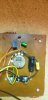
Crossover (recapped) is depicted, as well. Yellow brown and green are the negative leads off the drivers. Black goes to the woofer, orange goes to the horn, and red to the compression driver.

Originally, one speaker had no output under any conditions from the horn or the compression driver. That has been fixed.

Next, I was getting nothing out of the tweeter and compression driver with the original pots unless I had the pots cranked all the way up. After multiple deoxit treatments followed by a faderlube treatment, still no improvement so I disconnected the pots and tested them on their own. They didn't seem to work the way I expected them to so I figured I had my culprit. Based on a few threads here and elsewhere, I picked up a couple of these to replace the original pots:
https://www.parts-express.com/L-Pad-15W-Mono-3-8-Shaft-8-Ohm-260-248

I realize they are not the same as the pots that were in these originally, but like I said, it appeared that's what I needed based on my reading. I could be way wrong but after installation I was pleased to find that I had output over the whole range of adjustments, and the adjustment was fairly effective. However, now the high end is too hot over most of that range. I get what seems like a reasonable treble setting somewhere around like 10% of the way through the adjustment range on the new L-pad.

I'm not any sort of knowledgeable about crossover design, nor am I looking to redesign the whole thing. Just want to get these working nicely, and reliably, to sell because they are too big for any space I have. The idea here is to make more of the available range of adjustment on the L-pad useful. And maybe also protect the high frequency drivers a bit since I'm thinking running them so hot might burn them up.

Is there a simple solution here or should I just leave it as-is?
 

Attachments

  • 20210426_130929.jpg
    20210426_130929.jpg
    116.8 KB · Views: 36
  • 20210419_230540.jpg
    20210419_230540.jpg
    69.2 KB · Views: 38
Last edited:
Register to hide this ad
More pictures may help. L-pads are dependent on the impedance of the driver, perhaps the one you purchased is not a match for the tweeter. I've replaced pots with L-pads and not had the issue you describe. Sometimes pots can be rehabilitated, but the few knowledgeable people who I've discussed the issue with prefer L-pads. Also, are those all original capacitors?
 
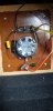
Thanks for the response! What additional pictures would be helpful? I added a couple, which show the dispersion foam I installed inside, and one showing my VP of operations and my executive director of audio engineering, doing what they do best.

I believe the horn is actually the "mid" driver in this 3 way design, with the compression driver doing top end duty. I had that wrong in my first post.

Those are replacement caps. Cap values are 8uf high pass to the L-pad and the horn, and then 4uF high pass to the tweeter. I hand measured the caps, and you can see I used poly bypass caps along side the electrolytics. Original design used electrolytic capacitors in both positions.

The L-pad is rated for 8ohm and the horn measures 10.4ohm with the compression driver measuring 7.2ohm. The speakers are nominally 8 ohm and the "good" one measured 7.4 when I brought them home.

My inclination is that a fixed resistor network "L-pad"...... BEFORE the actual L-pad that I installed, would do what I need, but my engineering brain says "Doubling the solution doesn't double the effect. Don't be dumb, Sam. Ask someone who knows."
 

Attachments

  • 20210411_140759.jpg
    20210411_140759.jpg
    83.6 KB · Views: 30
  • 20210411_140755.jpg
    20210411_140755.jpg
    76.5 KB · Views: 31
  • 20210411_134551.jpg
    20210411_134551.jpg
    93.8 KB · Views: 29
I was suggesting more pictures just for the sake of getting more information on the drivers. As far as the L-pad goes, in my admittedly limited exposure, I think they are normally the LAST thing in the crossover before the speaker. Hopefully others will chime in, I always still look at connection directions before hooking up L-pads. I believe your picture shows the original potentiometer and connections, correct? The L-pad may need a different arrangement If so a picture with the L-pad may help. Yes, do NOT double up on L-pads.
Maybe open up the pots to see what they look like inside, they may be repairable.
Not too many bikes on the road with toe straps and down tube shifters.
 
I was suggesting more pictures just for the sake of getting more information on the drivers. As far as the L-pad goes, in my admittedly limited exposure, I think they are normally the LAST thing in the crossover before the speaker. Hopefully others will chime in, I always still look at connection directions before hooking up L-pads. I believe your picture shows the original potentiometer and connections, correct? The L-pad may need a different arrangement If so a picture with the L-pad may help. Yes, do NOT double up on L-pads.
Maybe open up the pots to see what they look like inside, they may be repairable.
Not too many bikes on the road with toe straps and down tube shifters.

The Miyata is still one of my main bikes but it is getting long in the tooth. It has over 10k miles on it now after 6 years of me riding it. It sports 2x9 dura ace downtube shifters and while I still have the toe clip pedals, I have keos on it these days to match my other road bikes. I love some quality steel.

As for the speakers, the L-pad comes after the woofer but before the midrange and tweeter signals go to their respective drivers. I assume this was so that the entire "upper" registers could be tuned with just one knob, rather than like in an AR2-AX with mid and treble control. electrically, it should be pretty much the same since the crossover is only a simple cap blocking lower frequencies. The woofer operates "full range" while the mid horn operates "full range" less the frequencies filtered by the 8uF cap, and then the tweeter operates with whatever is left after the 4uF cap. This actually makes zero sense to me, though, which is why I figured I should get on here to get some help.

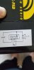
The prior pictures show the old pot in place. I am attaching pictures to this post that show the new L-pad attenuator "pinout" and how I have it installed. I hadn't considered that I might have it wired wrong since it seems to have the effect it is supposed to (i.e. turning it "up" increases treble), but I guess that's a possibility... I thought I was following the diagram properly... I don't know that significance of the little loop shown on the diagram between the 2 and 3 lugs, though. Nothing with the L-pad explains that. Possibly supposed to have a bleeder resistor there?
 

Attachments

  • 20210427_134426.jpg
    20210427_134426.jpg
    46.8 KB · Views: 26
  • 20210427_134447.jpg
    20210427_134447.jpg
    100.4 KB · Views: 28
Last edited:
An L-pad and a pot do their jobs differently. I've used the same L-pad and not had the issue you're having, though I've never tried to control two speakers with one L-pad. My comment was based on never seeing an L-pad anywhere but the last component before a driver. I'm not a guru, but I've been studying crossovers for several years and will say things are often not as simple as they seem. On the other aspects, woofers are often left to run full range, how good that functions depends a great deal on the woofer, inductors tend to be relatively expensive. That the mid horn does not use a band pass filter could be a cost consideration in design, again how well it works in real life depends on the driver. That little loop in the L-pad diagram probably represents the sweeper.
For the record, all my rides are steel though I did have a Klein for about twenty years.
 
L-pads are supposed to represent a consistent load to the driving voltage, correct? Whereas a plane-jane pot is more-or-less a variable resistor, yeah?
the loop representing the wiper makes sense. I should have thought of that.

Perhaps the lower ESR of the new caps is part of the culprit... :idea:

These Utah speakers were not high end. Decidedly mid-fi when they were made in the late 60s through the early 80s. I believe these to be around 1972ish based on a few discussions I have had with people locally, including my dad, these were "budget" speakers...
"I bought mine in '71 or '72. People always wanted the AR or the Advent. By this time the KLH models weren't as common at stores and people thought they were old technology and the 'bigger is better' notion had set in. But if you couldn't swing the $275 for the Advents or more for the AR speakers, you got the Utahs. The sticker price was always $200 but no one ever paid that because they were basically always 'on sale' for $100. We all knew they weren't really $200 speakers but it made you feel better that they said $200. And we thought they looked pretty good."

So anyway, I wouldn't doubt that there were significant cost-oriented compromises made in the design and execution with these. Utah was also a driver supplier to other manufacturers, so they weren't as focused on engineering their own speakers to be absolute performers as they might otherwise have been. Cabinets aren't of the quality you find in KLH, AR and other higher end speakers of the day, magnet mass is much lower, crossover design is rudimentary, etc...

Hopefully someone will come along soon and advise.

BTW, love the avatar. Also in my collection of metal bikes are a 1992 Burley Duet tandem made of True Temper steel, and a 1994 David Lynskey built titanium Litespeed. My fiancee rides a 1988 Panasonic DX5000 or a more recent steel offering: Brooklyn Roebling... a nice little city bike!
 
Last edited:
L-pads are supposed to represent a consistent load to the driving voltage, correct? Whereas a plane-jane pot is more-or-less a variable resistor, yeah?
the loop representing the wiper makes sense. I should have thought of that.
Now you're using your grey matter.
In my experience the lower ESR of new caps doesn't have as large an effect on brightness that you describe.
1988 Santana Elan, also True Temper, but straight gauge. Heavy sucker. DX5000, I'm not sure one could go much higher on the Panasonic food chain.
 
Just looked over a couple of DIY sites. One could get into a pissing contest about this but the most significant note that I saw is that putting the L-pad before the filter exposes the L-pad to full load of the amplifier. This would require an L-pad rated to take a higher wattage, and be much more expensive. As yours are 15 watt units this could be a argument for putting the L-pad in a different arrangement. If the original pots aren't fried you may be able to rehabilitate them. See if they're not to hard to disassemble.
 
Next, I was getting nothing out of the tweeter and compression driver with the original pots unless I had the pots cranked all the way up.
That's a 10,000 Ohm pot!

Is it possible that original 10 Ohm pots were mistakenly changed out in the past with 10K pots? I'm no crossover guru, but pots I've seen in passive crossover networks are typically rated in the 10's of Ohms.

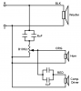
Here's how it appears your crossover is configured based on the photo.

Utah_xover_sch.png
[edit -- added capacitor values]

Can't make out capacitor values, though it's curious to see what appears to be a poly bypass cap on each high pass filter cap. Could this be evidence of earlier rework to the stock crossover?
 
Last edited:
Better eyes than mine Stuart. Could be why there was no output for most of the range? Being budget speakers maybe they were just for show and used whatever they found cheap. @klamsoss perhaps you can tell us the values of the caps and what readings you got off the pots?
 
In post 6 yesterday I tucked away the cap values. 8 uF for the "first" one (that would be the "top" one in your diagram) and 4uF for the "2nd/bottom" one.

I believe the depicted layout is correct.

The caps in the photo are new, installed by me, and replicate the values of the original two electrolytic capacitors that were in the speakers when I got them. It's definitely possible that some work was done to them previously. There is evidence that the woofers were removed prior to me taking them on.

As for the original pots, one is physically broken from my efforts to disassemble while the other is in okay shape. I had basically the same reaction as stuart when I found an 810k pot in there. I'm not opposed to rearranging things, or changing some values around, but I don't really want to get into trying to design a new crossover. I don't have and doubt TS parameters are readily available for the drivers, and I don't know how to design crossovers anyway. Also, as previously mentioned, I'm not wanting to spend a lot on some cheap speakers I'll be getting rid of. I just want their new owners to have a reliable pair. I don't like selling stuff that has known fundamental flaws.
 
Last edited:
In post 6 yesterday I tucked away the cap values. 8 uF for the "first" one (that would be the "top" one in your diagram) and 4uF for the "2nd/bottom" one.

Ah, so you did. Must learn to actually look at what I'm reading ...:confused:. Updated the schematic for posterity.

The found 10K linear taper pot was wired as a voltage divider, rather than as variable series resister (rheostat) often seen in crossover circuits. As such, any degree of rotation would proportionally reduce output voltage identically to a 10 Ohm linear pot. The only difference is amount of current limiting. A 10K pot reduces output current a lot compared to 10 Ohms, beginning immediately into counter-clockwise rotation -- up to 1000 x less current at full attenuation.

The question becomes: how much current is needed to move diaphragms of your higher frequency transducers sufficiently to make sound?

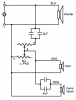
Your installed L-pad is also a voltage divider, with each of its resistive elements only measuring a handful of Ohms at any setting. An L-pad is designed to maintain a constant output impedance to match a target load impedance. It's probably not seeing an 8 Ohm load impedance in your configuration, which might explain why it's not behaving entirely as expected, though it does attenuate successfully across part of its travel. The fact that you get audible sound throughout with this relatively low resistance device supports the notion that the 10K pot originally found was not correct.

Whether or not the best solution, your L-pad does appear to be installed correctly with respect to orientation between "source" and "load." Here's the modded schematic, ... because posterity.

Utah_xover_L-pad.png
 
@Stuart Pedaso your drawing is great!
Your explanation is also excellent, as well! Without readily available schematics for the original design (if those even ever existed) or any other identical speakers that are known to be untouched, your supposition that the 10k pot isn't original is the best available explanation that fits the available information. It sounds like something like the pair of 25-ohm pots that @Guido57 generously offered me would be suitable replacements for the L-pads that I've installed, and would probably give me a more useful range of attenuation.
Thank you both for the help here! This is what makes AK a great community!
 
Back
Top Bottom