• The move to the new server is done. There are some software and database maintenance updates in process. This has us passing the hat around to help out. We appreciate any donations. Seriously, even a dollar helps. The payment page may be found here - https://www.audiokarma.org/support.html

Crossover Upgrade Help

canuckken

Active Member
I am trying to revive an old set of speakers that have electrolytic caps. The crossover has a Pot which I would not mind removing from the circuit, is that a good thing or should I leave it alone? I was never a fan of tweet pots, I have always assumed that its an extra added to the circuit that's not needed but I am a novice and often my assumptions are wrong. I am second guessing myself, without hearing the speakers or measuring them one would not know what to set the tweeter cap and resistors value at so in that sense perhaps I should leave things as is?
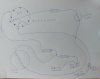
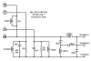
I am going to attach a diagram that I made of how the crossover is wired, I believe if I was to remove the pot I would need to replace it with a resistor? how does one know the value, do you base it on the cap value or is it trial and error?
Please keep your answers as simple as possible so I can understand, like I said, I am a novice and still learning this stuff, if your willing to drawl me a new schematic, that would be even better and I would return the favor somehow, any help is appreciated.
 

Attachments

  • 20220312_091749.jpg
    20220312_091749.jpg
    55.5 KB · Views: 65
Register to hide this ad
So crossovers of course are filters to divide the sound energy between the low and high frequency drivers.
But they also help blend the sound produced by both so that they play well together in a way where you don't hear them individually but as one.

A visual analog would be getting a seam in wallpaper to match perfectly, or better yet matching the color of two shades of paper.
Anyway, so the two speakers have curves where their output is plotted over frequency. You've seen them. So the crossover comes into play at the seam.
But for the two curves to sound like one -a "flat" transition- the points on the curve have to be close in amplitude at the seam, and across the whole range of frequencies.

I'll cut to the chase... the tweeter may be louder, which would mean no seamless transition and no harmony or blending of the two speakers. You need a resistor to "pad" the tweeter.
So a pot could be compared to a brightness control on the tweeter to blend it at the seam like the two sheets of white paper from the analogy.

So you can replace the pot with a resistor, but it would be needlessly difficult to do any calculation on what the value should be. The easiest way to determine the value would be with your ear*.
And then you measure the value and replace the pot with a resistor.

Or just leave the pot where it is.


*Edit: The pot is there because the brightness of a speaker is a matter of taste to many. If you really want to though, you could play pink noise through the system and tweak the output while looking at a spectrum analyzer.
 
Last edited:
I understand what the pot is for, I was just hoping that there might be an easy way to determine what resistor value to use to replace it, seeing how there is no easy way (at least for me, I don't have a spectrum analyzer), I will leave it in the circuit. Thanks.
 
It would be very helpful to know brand and model of the speaker. It makes it easier for others to give good advice.

Your sketch cannot be correct. You show a 4.7 uF cap in series with the woofer. If anything is in series with the woofer voice coil, it will be an inductor, which is the typical low pass filter. If there is a cap in series with the woofer VC, it will be on the order of several hundred uF because it will be acting as a high pass filter with a VERY low crossover frequency.

Since you say you are a novice, I suggest redrawing your sketch as a schematic using conventional symbols. That is a good way to learn. See this web page for good crossover info: http://www.bcae1.com/xoorder.htm

As for replacing the pot with a resistor, the best way is to position the pot for the best sound and then measure the resistance (out of circuit) between the center tap and each of the two connections. Then wire the two resistors to replace the measured resistance.
 
Pretty sure I drawled it correctly and the 2 caps for the woofer are 4.7uf.
The speakera are sound dynamics 10s which I doubt many members have seeing how they are not considered to be great speakers by most.
 

Attachments

  • pic.jpg
    pic.jpg
    124.6 KB · Views: 59
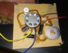
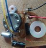
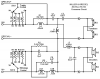
This is the other crossover, might be a little hard to see but the coil definitely connects between the 2 4.7uf caps so if it is wrong than the manufacturer wired them incorrectly.
 

Attachments

  • 20220312_075647.jpg
    20220312_075647.jpg
    136.2 KB · Views: 49
These are the speakers
 

Attachments

  • 983077-77b2487c-sound-dynamics-10s-pair-of-speakers-with-original-box.jpg
    983077-77b2487c-sound-dynamics-10s-pair-of-speakers-with-original-box.jpg
    51.1 KB · Views: 45
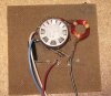
OK, I am really confused now, I just found a crossover from the same speaker that was designed completely different and much more simple but the woofer has no coil, just a 4.7uf cap.
 

Attachments

  • Original crossover.JPG
    Original crossover.JPG
    153.3 KB · Views: 33
The pictures of your crossovers show a mess. It looks like someone thought they could do better than the factory and wired a bunch of crap. It is not a traditional crossover.

Your original drawing does not show the connections to the drivers (woofer & tweeter).
Your pics show that the woofer has no crossover (I assume the red and black wires go to the woofer). That is, the woofer has a straight connection to the speaker terminals.
I assume the black (or green) and white wires soldered to the pot go to the tweeter.

If you are lucky, you find someone who has these speakers and can make a good wiring diagram as they came from the factory.
 
The pictures of your crossovers show a mess. It looks like someone thought they could do better than the factory and wired a bunch of crap. It is not a traditional crossover.

Your original drawing does not show the connections to the drivers (woofer & tweeter).
Your pics show that the woofer has no crossover (I assume the red and black wires go to the woofer). That is, the woofer has a straight connection to the speaker terminals.
I assume the black (or green) and white wires soldered to the pot go to the tweeter.

If you are lucky, you find someone who has these speakers and can make a good wiring diagram as they came from the factory.

Ok, thanks for the input. I don't know about someone messing with the crossover and trying to make it better, it sure looks like original glue and the board was not damaged by someone trying to pry components off, not to mention that the old electrolytic caps look original. It is almost impossible to remove anything from the board without destroying what you are trying to lift and if something was removed it would leave the glue trace behind or pull a layer off the board or the component, I am not saying that you are wrong, just that my eyes are not seeing that someone tried to modify the board because there would be damage and any damage that was done was done buy me when I was prying the board from the speaker. If they replaced the board, they did a very good job of removing the stickers on the back binding post plate and reattaching them.
I will try to find someone with the same speakers and see if they can help me.
By the way, you are correct about the placement of the wires, I will attach the same crappy drawing showing the wires.
 

Attachments

  • 20220312_234352.jpg
    20220312_234352.jpg
    48.9 KB · Views: 29
Last edited:
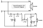
Here is a schematic for your speaker:
Sound Dynamics 10s.png
From what I can tell, you traced it out accurately, but misidentified the larger coil and its associated caps as belonging to a woofer filter. As RTally points out, the woofer connects directly to + and input terminals, hence it is running free without a filter. The two 4.7µF caps along with the coil are configured as what's called a 3rd order high pass filter. It cuts off low frequencies from reaching the tweeter at a fairly steep slope.

What you refer to as a "pot" is actually an L-Pad. It serves the same essential function as a potentiometer -- adjusting tweeter level relative to the woofer. But an L-pad maintains the same load impedance seen by the crossover filter no matter what level it's adjusted to. A pot does not.

Notice that the L-pad actually contains two variable resistors that are being adjusted simultaneously. The one on the left is wired in-line (series) with the tweeter and the other is across (parallel to) the tweeter.

Tweeter level controls are designed in to compensate for variations in room acoustics. A highly reflective space may result in high frequencies sounding too bright. A well padded room, and/or speaker placement that promotes bass reinforcement, could result in dull sounding high frequencies.

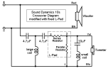
It's not too hard to substitute this level control with a fixed level setting that suits your listening environment. You'll need to measure and then replace the variable L-Pad with a fixed L-Pad consisting of two resistors. Resulting circuit looks like this:

SD10s fixed Lpad.png

It only requires an Ohm meter to find the resistor values needed.

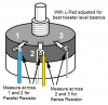
Start by placing speakers where they're likely to be used and spend some time adjusting tweeter level to find a setting with most satisfying performance. Pull out the crossover and disconnect the L-Pad wires without disturbing its setting. Measure across terminals 2 and 3 to find value of Series Resistor needed, and across 1 and 2 for the Parallel Resistor.

SD Lpad meas.png

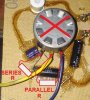
Source resistors that are closest you can find to the values measured. With stock L-Pad disconnected, solder one lead of the Series Resistor to the 4.7µF cap lead that was removed from the L-Pad. Solder the other Series Resistor lead where the 10µF cap connects to the Yellow wire, along with one end of the Parallel Resistor. Solder the other end of the Parallel Resistor to the Blue wire and the jumper wire to "" input terminal. Button them up and enjoy some music.

SD LPd replace.jpg
 
Last edited:
OK, I am really confused now, I just found a crossover from the same speaker that was designed completely different and much more simple but the woofer has no coil, just a 4.7uf cap.
Sometimes various iterations of a speaker model evidence evolution of the crossover during its production life. A good example recently discussed in these forums is the Miller and Kreisel Satellite-1. Its circuit began life looking like this:
schem_S-1 sch.png

By three iterations later, it had evolved to this:
schem_S-1Bsw.png

Though the core dividing circuit remained identical, much of the ancillary features had changed.

There may have been a similar progression in the Sound Dynamics speaker design.
 
Last edited:
Here is a schematic for your speaker:

View attachment 2510931

From what I can tell, you traced it out accurately, but misidentified the larger coil and its associated caps as belonging to a woofer filter. As RTally points out, the woofer connects directly to + and input terminals, hence it is running free without a filter. The two 4.7µF caps along with the coil are configured as what's called a 3rd order high pass filter. It cuts off low frequencies from reaching the tweeter at a fairly steep slope.

What you refer to as a "pot" is actually an L-Pad. It serves the same essential function as a potentiometer -- adjusting tweeter level relative to the woofer. But an L-pad maintains the same load impedance seen by the crossover filter no matter what level it's adjusted to. A pot does not.

Notice that the L-pad actually contains two variable resistors that are being adjusted simultaneously. The one on the left is wired in-line (series) with the tweeter and the other is across (parallel to) the tweeter.

Tweeter level controls are designed in to compensate for variations in room acoustics. A highly reflective space may result in high frequencies sounding too bright. A well padded room, and/or speaker placement that promotes bass reinforcement, could result in dull sounding high frequencies.

It's not too hard to substitute this level control with a fixed level setting that suits your listening environment. You'll need to measure and then replace the variable L-Pad with a fixed L-Pad consisting of two resistors. Resulting circuit looks like this:

View attachment 2510939

The Series Resistor is measured across L-Pad terminals 2 and 3. Parallel Resistor across 1 and 2. It only requires an Ohm meter to find the resistor values needed.

Start by placing speakers where they're likely to be used and spend some time adjusting tweeter level to find a setting with most satisfying performance. Pull out the crossover and disconnect the L-Pad wires without disturbing its setting. Measure across terminals 2 and 3 to find value of Series Resistor needed, and across 1 and 2 for the Parallel Resistor.

View attachment 2510967

Source resistors that are closest you can find to the values measured. With stock L-Pad disconnected, solder one lead of the Series Resistor to the 4.7µF cap lead that was removed from the L-Pad. Solder the other Series Resistor lead where the 10µF cap connects to the Yellow wire, along with one end of the Parallel Resistor. Solder the other end of the Parallel Resistor to the Blue wire and the jumper wire to "" input terminal. Button them up and enjoy some music.

View attachment 2510998
This is the right way to do it. An L-pad configuration and not just a single resistor because that would change the crossover point.

This is a good site for learning and understanding how L-pads work.
http://www.mh-audio.nl/Calculators/att.html
 
Yeah I admit I didn't even look at his first schematic and wrongly pictured the single resistor and cap to tweeters used in cheap speakers for some reason. But of course they don't use pots in those cases. Oh well, too late to change my answer.
Very thorough response by Stuart.
Is that draw program you're using freeware by any chance? Nice.
 
Wow! you guys rock, I was beginning to think that I was just going to wire it the way I traced it out and hope for the best. I learnt some thing from just making this thread and to me that is worth a lot. I have decided to leave the L-Pads, I figure with the new caps and coils I just ordered, the speakers will be improved and if I ever decided to sell the speakers (I don't think I will) it would be nice to have the speakers stock (minus the original caps and coils) for the next person.
I was glad that I bought an LCR tester, I would have been lost for the coil values without it.
Stuart, I really owe you man, you went beyond and above with the help and I thank you for doing it, not only did you give a schematic, you took the time to explain things so that an old guy could understand and to top it off you even addressed my question about the two different crossovers for the same speaker.
I will be able to sleep well tonight knowing that I will wire my crossovers correctly.

coonmanx, a big thanks to you also for pointing out about the L-pad being correct and giving the link, I will be sure to check it out.

thesteve, I have not forgot you, a big thanks to you also for your explanation.

And last but not least, RTally, your input was also appreciated, your post made me scratch my head a few times but not in a bad way even though I was actually thinking the speaker engineers had messed up the crossovers, I knew I had not messed with them and the guy that I bought them from was the original owner and he did not mess with them either, thus why I was beginning to think Sound Dynamics made a big mistake with this crossover design, none the less, you took the time to reply when you could have remained silent, while I got the ball rolling, you helped speed it along and even made me dig a little deeper in using google, I found the picture of the other crossover because of the things you wrote and that was important.

I can't say enough good things about Audiokarma members, this site is invaluable and has helped me more than any threads or post I have created just by reading threads that others have made about various topics, for now, life is good, I wish I could say the same for those in the Ukraine.

Take good care everyone.
 
Last edited:
One final question about the crossovers if you all don't mind. Someone mentioned to me that it might be better to use 2 x 20uf caps in series in place of the 10uf cap, is there any advantage to that or am I fine just using the 1 x 10uf cap?
 
One final question about the crossovers if you all don't mind. Someone mentioned to me that it might be better to use 2 x 20uf caps in series in place of the 10uf cap, is there any advantage to that or am I fine just using the 1 x 10uf cap?
Seems to me two caps in series just doubles the ESR (equivalent series resistance) compared to a single cap. Though maybe there's some other consideration I'm not aware of that would make the series arrangement preferable?
 
Seems to me two caps in series just doubles the ESR (equivalent series resistance) compared to a single cap. Though maybe there's some other consideration I'm not aware of that would make the series arrangement preferable?

I asked what he meant and he told me that someone had solder in a Polarized Electrolytic Capacitor which they should not have done so that is why he suggested the 2 electrolytic caps but when I mentioned that I purchased film caps he said all was well.
 
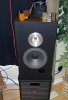
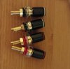
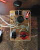
So I have the speakers completed, I notice an improvement in the bass and clarity, these are actually pretty good sounding speakers, at least I am happy with them. Here is a couple of pics, I know the hot glue makes the crossover look crappy but I did not care much about how it was going to look, no one ever sees the crossovers. I like the binding post, only thing that is magnetic is the screws but I remove them anyway.speaker.jpg binding post.jpg crossover.jpg
 
Back
Top Bottom