• The move to the new server is done. There are some software and database maintenance updates in process. This has us passing the hat around to help out. We appreciate any donations. Seriously, even a dollar helps. The payment page may be found here - https://www.audiokarma.org/support.html

DCM TimeWindow Seven clone project

JHauser

Active Member

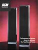
DCM TimeWindow Seven clone project.
TW7a.jpg

DCM plaque25%.jpg

This is something that I’ve wanted to do for years and for many reasons. These are remarkable speakers and as Steve Eberbach has said, that they took the TimeWindow technology as far as they could go. Truly his "signature" series.

I've been collecting parts for about 3 -4 years. I have all of the original drivers, OEM grill cloth and critical crossover parts along with most of the original hardware. I recently brought my TimeWinow Seven's into my workshop to replace the electrolytic caps, I took the time to make a complete set of working drawing from them. After talking to Steve, the only deviation I will be making from the originals would be to upgrade the film caps from polyester (Mylar) to polypropylene.

They have been a challenge to build, not just with my limited resources, but to find as many of the original parts and keep it as close to the original design as possible. Because they are such a complex design and without the original test equipment (or the knowledge of how to use it), my success is completely dependant on matching what was done at DCM. I don’t have the luxury of straying off for the sake of convenience. What very little I have (small improvements) was done with Steve’s advice.

My ultimate goal here was to have four matching TW7’s in a quad formation (4.1) for multi-channel music (I’ll still maintain the center for 5.1 multi-channel and 11.1 for home theater). In particular for Alan Parson's quad mix of DSOTM. The cleaned-up version in the new "immersion set" is extraordinary. It really is all about the music.

I'm going to start out with showing some photo's of the original TW7's when I had them in the workshop to be re-capped. One was partially disassembled in order to take measurements for the construction drawings needed to build the cabinets later and also to document the overall design.

This also gave me the opportunity to build some sub-assemblies while I could make direct comparison, in particular the crossovers, The TW7's crossovers are probably the most complex ones ever designed, with 45 components spread over three areas. Having the schematic is one thing, but it would have been very difficult to build one without a model to go by. I was also able to build the wiring harnesses, and the unique felt design between the tweeter screens. I will go into detail later.

The TW7's also use polyfill in four locations. They were made from bulk fill wrapped with a 24x 24 x 1/2 thick piece. I removed and weighed each one and made similar, which I bagged and documented there location for later use.

2.jpg
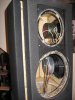
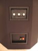
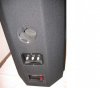
Here is the rear of the speaker showing the terminal cup that also holds part of the crossover on the backside and the Spectral Balance controls. The outer port tube is removed along with the end caps and fluted sidepieces

IMG_0154.JPG
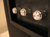
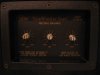
A close-up of the Spectral Balance controls without the knobs.

3.JPG
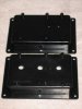
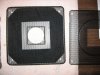
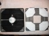
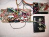
And the three pieces of the crossover network.

4.JPG
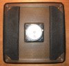
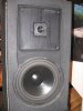
Here are a few with the grill cloth pulled half way down showing the drivers.

5.JPG
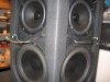
First with one of the tweeters and grills in place, then next with the grills removed showing the 6-1/2 midrange drivers behind,

6.JPG
and finally the rear-firing tweeter.


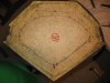
Here are some shots of the top of the cabinet showing the corner construction.
7.JPG
View attachment 1307664

9.JPG
 
Last edited:
Register to hide this ad
10.JPG
Some more with the inboard/direct sound field midrange and woofer removed,


11.JPG

12.JPG
and a couple of close-ups.


Some interior shots
13.JPG
14.JPG
15.JPG

And lastly, one of the four batting assemblies
16.JPG
17.JPG

18.JPG
 
Last edited:
So it begins:

Top-Base Drwg.jpg
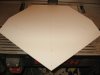
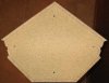
The first photo is a close-up off one of the construction drawings of the top and base that are overlap on one sheet because of their similarities in shape and mounting points. The purpose of the photo is to show the transfer of key points in the drawings with needle pins to a light cardboard stock that will be "re-drawn" for use as router patterns.

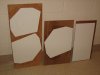
Patterns.jpg
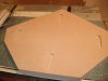
The next picture is of the cardboard stock adhered to ¼" plywood scrap that will be trimmed down to the exact shape.

Unassuming wood.jpg
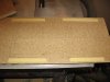
Last is a photo of a stack of unassuming wood, not knowing of the fate in store for it.

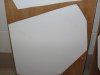
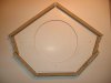
Here are a few close-ups of the patterns.
Top Pattern.jpg

Front Baffle Pattern.jpg

Brace Pattern.jpg


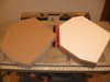
Here are some of the templates that are done:

Front Baffle Template.jpg
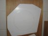
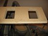
The front baffle is made up of two pieces of ½" particleboard laminated together. The inner one has the cut outs for the 6-1/2" midrange and 9" woofer. This is for the outer one.

Top-Bottom- Bracing Template.jpg
The next is a template for making several pieces. Two for the top and bottom to seal the cabinet (not the piano black caps or bases) and will use just the four ¼" holes for mounting the piano black caps or bases, two for internal bracing/quasi transmission line design that will only have the single 8" hole, and one that separates the midrange section (top 8" of cabinet) from the woofer section (an additional ½" will need to be trimmed from both baffle edges as shown with the scribed lines).

Base Template.jpg
The last is the base template showing the locations of four mounting holes along with the locations for the spikes.
 
Last edited:
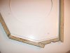
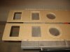
I finished making the side panels for the cabinets, (there's seven per speaker) but I need to router the cutouts for the drivers, port tubes and terminal cups yet. After trimming them for length, I used the drops to test the fit-up with the template that will be used to make the end caps and bracing. The pictures show the complexities of the cuts.
panel fit-up1.jpg

panel fit-up2.jpg

corner detail.jpg


Probably the most time consuming piece to make (at least for me) was the back panel with it's vee'd edges, but mostly because it incorporates the two terminal cups and rear firing tweeter cut-outs (both were also recessed) and the port tube (there is a 4" hole for the plastic port tube to slides in, but also a ¼" recess that the 5" inner cardboard port tube mounts to on the inside). Also added is the time needed to make required templates.


Cab Build_007.jpg
The layout for the terminal cups showing the two-way tape to hold the template

Cab Build_008.jpg
Template in place.

Cab Build_010.jpg
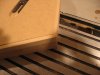
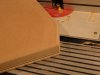
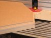
The bulk of the material removed with a template guide and ¼' router bit.

Cab Build_011.jpg
Finished off with a flush trim router bit.

Cab Build_019.jpg
Both panels finished with one showing the reverse side (note the ¼" recess for the 5" inner cardboard port tube mount).

Cab Build_020.jpg
Tweeter cut-out.

Cab Build_002.jpg
Rear tweeter temporally mounted to check fit.
 
Last edited:
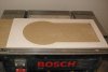
The next thing to do is router in the cut outs for the drivers.

Cab Build_001.jpg
Here is the template for the outer front baffle using double sided tape to hold it place before
the bulk of the material removed with a template guide and ¼’ router bit.


Cab Build_005.jpg
After being trimmed.

Cab Build_012.jpg
This photo is with the outer baffle temporally clamped to the inner baffle and a cardboard template inserted to transfer (using a prick punch) the center hole locations for the driver cut outs, driver screw mounting locations, tweeter grill screen screw mounting locations, and hole for tweeter wires.


Cab Build 017.jpg
Inner baffle partially router.


Cab Build_018.jpg
Finished outer baffle on top of inner baffle.


Cab Build 073.jpg
The template was used to trace out the lines needed to cut the blanks from the ½" particleboard on the table saw.


Cab Build 077.jpg
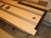
The stack of blanks ready to be trimmed on the router table. Only four (two per speaker enclosure) will have the 8" hole in the center.


Cab Build 079.jpg
A finished brace with the template still attached and a blank next to it.

Here are the last pieces for the cabinet:

Cabinet Build 090.jpg
The top and bottom end caps. Note the T-nuts that are for mounting the black decorative top and base


Cabinet Build 092.jpg
Inner partitions. The one on the left has an additional 1/2" trim from the edges that face the front baffles.
 
Last edited:
port.jpg
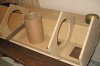
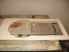
This is the inner 5" ID cardboard port tube and brace. The brace is attached to the two front baffles


Cabinet Build 084.jpg
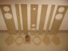
This last photo shows all the pieces in order before assembly. The long piece in the middle is the rear of the speaker and the other pieces wrap around until the front baffles (large outer pieces on the ends) meet. Pieces on the floor are bottom on the left to top on the right.


It took a little while to decide on how to assemble everything and keep everything square. After checking with Steve E., he gave me the order of assembly, but DCM used a jig to keep everything in alignment. Not wanting to go to the effort to build one (seeing that I’m only assembling two), I came up with a relatively simple solution.

Cabinet Build 093a.jpg
What I did was flip the three back pieces over, line them up tightly, and duct taped the two joints together. The whole edge on both ends could be sanded to square with all three pieces as if they were all one piece. This would eliminate any accumulative error with misaligned /out-of-square pieces assembled individually.


Cabinet Build  096.jpg
Next, the three pieces are flipped back over and lines locating the partitions/braces are scribed in.


Cabinet Build  099.jpg
After that, it’s just a matter of running a bead of construction adhesive inside both joints and pulling the two sides together using duct tape to temporally hold them up. Then, one at a time, starting with the end caps, then the internal braces, apply the same construction adhesive and attach them with 1" long, ¼" heat-adhesive crown staples. The duct tape did an excellent job holding the pieces in alignment and keeps the joints uniform and relatively tight. Steve mentioned that you really don’t want a joint that is to tight as in clamping, but up to 1/16 of an inch, and never less than a few thousandths of an inch, to help with the sound deadening.


Cabinet Build  101.jpg
After glued and stapled.


Cabinet Build  125.jpg
Another shot, standing up.


Cabinet Build  104.jpg
Next with the narrow strips were added that hold the decorative piano black fluted sidepieces. Note the T-nuts that are needed for the Mod-eez fasteners for the fluted sidepieces.


Cabinet Build  109.jpg
The inner 5" port tube is hot glued in place like the original. I don't know why hot glue was used in this particular case when a construction adhesive is used elsewhere. The CX-17 cardboard port tubes were also done the same way. I guess I'll have to ask Steve


Cabinet Build  112.jpg
One of the front baffles dry fitted.
 
Last edited:
Cabinet Build  114.jpg
After glued up.

Cabinet Build  120.jpg
This one shows setting up the brace for the other end of the port tube, it attaches to both front baffles and the tube is also glued to it. I don't know how the factory did it, but this worked. After the adhesive set up, I added a couple of temporary braces underneath just to be safe, then glued it up with everything else before I set the last baffle. Before setting the last baffle, Steve said that the stuffing, crossovers and wiring would be put in place. I decide to hold off because the crossovers aren't quite finished yet, I still have to make and fit the tops, base and side pieces, and even though it might be tougher, I can still access every area without the drivers in place.

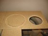
Here are some random shots of the one completed cabinet. I'll assemble the other in the next day or two, then probably start on the tops, bases and side panels.

Cabinet Build 161.jpg

Cabinet Build 158.jpg

Cabinet Build 160.jpg

Cabinet Build 143.jpg

Cabinet Build 139.jpg

Cabinet Build 154.jpg

Cabinet Build 150.jpg

Cabinet Build 152.jpg
 
Last edited:
Continued:

Cabinet Build 142.jpg


Cabinet Build 136.jpg

Cabinet Build 135.jpg

Cabinet Build 163.jpg
This last one, I added the Mod-eez screws to the top of the cabinet and did a trial fit with one of the original tops off one of my TW7’s

and then there were two.
Cabinet Build 186.jpg

Cabinet Build 187.jpg


At this point, the only comparison (photo wise) is the top shot, because it's the only picture of the original cabinet that is not covered with headliner material. Although I pretty confident the new cabinets are very close to one of the originals (right speaker) that I took very close measurements from. I believe I'm within 1/16 of an inch to those measurements in most regards.
Org top.jpg
new top.jpg
 
Last edited:
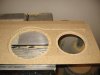
I started building the tops and bases. They are made from MDF and are approximately 1-1/4" and 1-1/2" thick, respectively. I could not find any reasonable source for those thickness', but could make them up by sandwiching ¾" and ½" for the tops and doubling up ¾" for the bases.

Cabinet Build 195.jpg
Using the two patterns to trace out the needed blanks and rough cutting them to size, here is one half of one of the bases being glued with Gorilla glue. I used a wide plastic scraper to spread it out to a thin even thickness over the entire surface. After that you wet the joining piece and clamp for 3 hours.

Cabinet Build 197.jpg
After they are set-up, the next step is to finish them off with a flush trim router bit. Here is one of the bases that is trimmed next to the one with the pattern taped on (note the centering holes for the mounting screws and floor spikes were transferred from the pattern to the base with a 1/16" drill). The tops were done in the same manner.

Cabinet Build 201.jpg
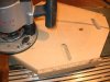
The tops need to have recesses routered into the underside for the Mod-ezz fasteners. I made a jig using some scrape plywood and used the plunge router with a template guide and ¼' router bit.

Cabinet Build 208.jpg
The underside of one of the tops with the recesses routered.

Cabinet Build 207.jpg
Mod-ezz clip screwed in place.

Cabinet Build 212.jpg
Next, there is a 1/16th" x 3/16" relief that is routered on the underside of the top.

Cabinet Build 215.jpg
Then a ¼" radius on the top edge.

Cabinet Build 219.jpg
The base has a ¼" radius cut made into the top edge that is a ¼" deep x 3/8" tall.

Cabinet Build 222.jpg
After that, the holes are drilled for the five spike locations (9/16" dia. x 7/8" deep, outer holes) and the four mounting spots (5/8" dia. x 5/8" deep with ¼" dia. hole through, inner holes).
 
Last edited:
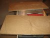
Trial fit of top and base.

Cabinet Build 225.jpg

Cabinet Build 230.jpg


The fluted sides were more work than I anticipated, but I’m happy with the results

Cabinet Build 192.jpg
They are 2-7/8" wide and were cut from 3/4" MDF stock. Because the backsides have an 18 degree bevel (which is an acute angle when you rip on a table saw) with a 1-1/8" land on the back and 1/4" on the sides, this required cutting the bevel with the piece on end. The only way that I could see to do that was to use double-sided foam tape and combined two pieces back-to-back. The photo shows one piece with the two bevels cut.

Cabinet Build 194.jpg
This photo shows the 1-1/8" land cut on one of the pieces.

Cabinet Build 249.jpg
Here are the four sides completed with the four 3/8" flutes that are 5/8" on center and a 1/8" deep. They stop a 1-1/8" from the top and 2-1/8" from the bottom. Also shown are the Mod-ezz mounting clips on the back of two of them.

Some misc. photos of the flutes in place.

Cabinet Build 238.jpg

Cabinet Build 242.jpg

Cabinet Build 246.jpg
Showing the mounting points.

Here's a picture of the original and the new.

Cabinet Build 235.jpg

Cabinet Build 234.jpg
 
Last edited:

The next step is to install the wiring harnesses and acoustical stuffing, which normally would have been done before the last front baffle, was put into place.

Cabinet Build 160a.jpg
The wiring harnesses are made up of three separate components. The main one is for the two 6-1/2" midrange drivers and the three tweeters. It is 57" long and made up of white, red, blue, brown, green, black, orange, and yellow NTE Electronics 20AWG, 300V, SP/25, STRND Hook-Up Wire.


The second is for the two 9" woofers. It is 43" long and made up of red, brown, black, and yellow NTE Electronics 20AWG, 300V, SP/25, STRND Hook-Up Wire.

There is a single 21" long wire that is black with a yellow strip that goes between the neg. side of the outboard tweeter to the pos. side of the rear tweeter.

All the ends are terminated with either FASTON 42068-1 (Stud/Tab Size:0.11 x 0.02"); or 42710-2 (Stud/Tab Size:0.205 x 0.02"); Crimp Connector Female Disconnect, Wire Size (AWG):22-18; Contact Material:Brass; Contact Plating:Tin, depending of what they're connecting to.

Cabinet Build 162.jpg

Cabinet Build 163a.jpg
Close up of the main harness showing the terminations.

Here are a few photos showing the harnesses installed.

Cabinet Build 166.jpg


Cabinet Build 165.jpg
This one is the main harness in the top section that houses the midrange drivers.
The second shot is the rear tweeter location in the same section.


Cabinet Build 164.jpg
And under in the woofer section.


Cabinet Build 292.jpg
This one shows both cabinets with the appropriate wires protruding were there drivers would be. Note that the color-coding of the wires are mirror image of each other. The penetrations into the midrange section and to the outside for the tweeters are sealed with hot glue like the factory did.

Also note the acoustical stuffing for both the midrange (7-1/4 oz.) and woofer (8 oz.) sections

There is also acoustical stuffing near the port tube and the filling the 8" hole in the first internal brace just above the section that holds the crossover board.
Cabinet Build 309.jpg


Cabinet Build 311.jpg
This is the left speaker were both wiring harnesses go pass the port tube on the left side. The acoustical stuffing (7-1/4 oz.) is pushed just pass the port tube on the right side filling the void between the port tube and the outside wall of the cabinet and the rest lays over the top of the tube. I did the reverse for the right speaker.


Cabinet Build 312.jpg
Here is the acoustical stuffing (7-1/4 oz.) filling the 8" hole in the first internal brace just above the section that holds the crossover board. The opening is completely filled with the bulk of the acoustical stuffing "mushroomed" above the opening.
 
Last edited:
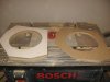
Next up are the crossovers.

This is really the only place were I'm making a slight upgrade and really only in a few ways. I'm staying with the original style wire wound cement resistors (made by Xicon) although tolerance will go from 10% to 5%. The electrolytic capacitors I'm using are made by ERSE and have a dissipation factor of 3% (except for the 200uF values which were only available with a D.F. of 6%) and tolerance of 5%. The original ones were 5% D.F. and 10% tolerance.

The biggest improvement (Steve's recommendation) is upgrading the original film capacitors from Mylar (polyester) with 10% tolerance 100v to polypropylene with 5% tolerance 250v. The new film caps are ECW-FA series Panasonic polypropylene film capacitors for all the values except the 3.0uF's which are the ECW-F series that are being phase out in favor of the ECW-FA series (this series does not have the 3.0uF value which I needed 8 of them for this project).

Crossover New 001.JPG
The circuit boards used are the C91's that are used in most of Steve's later designs like the CX and TF series. These were donors stripped down from several crossovers that I have acquired through the years.


Crossover New 002.JPG
Here are all the inductors needed (I'm still short two of the largest ones) for the new crossovers. These are the most critical part of reproducing any of Steve's design because they were unique and made by DCM. Particularly their powder iron cores. In the little bit of studying (reading and talking with Steve) that I have done, trying to find a suitable replacement, I found that iron cores are different that inferior ferrite cores and that there are many different mixtures for iron cores that have an impact on how the inductor performs.

Steve put a lot of work in designing these and I quickly realized that I could not build a substitute, I could only take the original inductors from donor DCM crossovers (there are 3 size based on core dia. and bobbin size) and strip the magnet wire and rewind them with the proper gauge magnet wire to the new values that I needed. I had to rewind all of them.


Crossover New 003.JPG Here's the start of 2 new boards.


Crossover New 005.JPG
This is one of the new ¼" plywood boards needed for the main board that is constructed with "Point-to-point" wiring next to an original.


Crossover New 010.JPG
Here is one of the sub-assemblies for that same board.


Crossover New 021.jpg
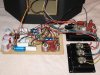
This is one of the completed crossovers (note that only the large inductors have hot glue on them. I will hot glue the rest of the crossover parts after everything is properly tested.


Crossover New 004.JPG
One of the original for comparison (note the additional wiring that goes to the drivers that are not shown with the new crossover above).


Miscellaneous close-ups.


Crossover New 030.jpg

Crossover New 027.jpg

Crossover New 022.jpg
 
Last edited:
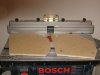
Back to the cabinets.

Cabinet Build  318.jpg
The baffle area surrounding the midrange and woofer along with the rear-firing tweeter needed to be blacked out.


Cabinet Build  326.jpg
After that the headliner material was applied. This is a 1/8" foam backed cloth that is attached with 3M Supper 77 multipurpose spray adhesive. Note the slot that is cut out were the Mod-ezz clips are used for the side panels. There is a full "sock" of speaker grill cloth that will be pulled over the entire cabinet later.


Cabinet Build  328.jpg
One of the cut outs for a terminal cup.


Cabinet Build  319.jpg
And another for the rear tweeter.


Installing the drivers are next. The TimeWindow Seven have a total of 7 drivers (possibly where the name came from, but it also has 7 sides for that matter). Two 9" woofers, two 6-1/2" midrange, and three tweeters.

Cabinet Build  325.jpg

Cabinet Build  320.jpg
The woofers are Vifa's M22WR-09-06 top-of- the-line (at the time) 9" drivers. Used in several other high-end home speakers, including the $12K Manger Zerobox and Apogee Centarus.


Cabinet Build  322.jpg

Cabinet Build  329.jpg
The midranges are DCM's D16 6-1/2" drivers that were used in the KX series. This is basically the same driver used in the CX and TF Series Two but with the plastic snap ring instead of a gasket on the outer rim of the basket and a magnet shielding cup over the main and bucking magnet. It was the last incarnation of that driver design. The dimpled cones used in all of them were made by a Japanese company for DCM. Don't let the stamped steel basket fool you, this is a remarkable driver Steve design and is good enough for his signature series TW7.


Cabinet Build  323.jpg

Cabinet Build  324.jpg
The two front firing tweeters are DCM D23 that are similar in appearance to the tweeters used in the CX and TimeFrame Series Two but are diamond coated and use a much larger magnet. These were unique to the Sevens and not used on any other design that I know of. The rear-firing tweeter was a DCM D22, which is the same as the D23 except for the lack of the diamond coating. Steve said that this was strictly for cost saving. I will be using the D23 for the rear tweeter.
 
Last edited:
Here are a couple of side-by-side comparison shots of all three driver types.

Cabinet Build  327.jpg

Cabinet Build  321.jpg


Here are a few random shots of the drivers being installed.

Cabinet Build  388.jpg

Cabinet Build  395.jpg

Cabinet Build  404.jpg

Cabinet Build  420.jpg

Cabinet Build  415.jpg

Cabinet Build  344.jpg
 
Last edited:
The crossovers, terminal cups and "Spectral Balance" controls are installed next.

Cabinet Build  456.jpg
The "Spectral Balance" controls are mounted on a modified terminal cup. This photo show the back side of a terminal cup that uses binding post as oppose to the ones with the spring loaded clips. The cup in front has the hole for the negative binding post filled (I melted/welded the same material into it from another terminal cup with a soldering iron) and sanded it out. The existing hole for the positive binding post is in the correct position for one of the variable resistor and just needed to be drilled out along with the holes needed for the other two variable resistors.


Cabinet Build  457.jpg
Here is the opposite side showing the variable resistors temporally installed (I used the nuts provided with them to hold them in place, the original ones are hot glued in place without the retaining nuts) and the fluted aluminum knobs. Those knobs were very difficult to track down and match to the originals. After about three years of on-and-of looking through online catalogs I was just about ready to settle for something remotely close just to do the job. I decide to Google "fluted aluminum knobs" but using the "images" option instead, and one of the first images was link to http://www.driveinmemories.com/index...products_id=26 for a perfect match and good price. It's funny how sometimes something that small of a find can give so much satisfaction.

The decal for the "Spectral Balance" control will be added later.


Cabinet Build  437.jpg
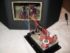
Here are the crossover components wired to the drivers.


Cabinet Build  446.jpg
The main board installed. It just slips into to tabs in the front of the cabinet and has a single screw that holds down the other end near the opening.


Cabinet Build  452.jpg
And finally with the terminal cup installed.
 
Last edited:
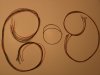
Next up in the project is to install the tweeters and their perforated metal grills. The grills are similar to the ones used in the CX series but deeper. They are the same as that used in the SurroundScape Center and possibly some of the TimeFrame series. They all used a single thick layer of felt sandwiched between the grills as shown in the first photo. Its purpose is for absorption and disbursement. The TimeWindow Seven's version is much more refined and tailored specifically to them. It also incorporates another material called Thinsulate made by 3M. I talked to Steve about the science involved and it's more than I can do justice in trying to explain here. He did say that it is addresses in one of his patents though. I was able to get the correct materials and with the originals as patterns, I was able to duplicate them with enough confidence to hopefully get similar results.

Below is the felt used in the CX and TF series.
Screens 5.JPG


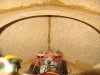
This one is the original TW7 opened up. The Thinsulate is the white material on the left. Notice that under the four black felt pieces, there are two longer pieces underneath.
Screens 1.JPG


Here is one of the longer pieces opened up to show a piece of Thinsulate sandwiched inside.
Screens 7.jpg


The following are the ones I made.


Screens 4.JPG

Screens 3.JPG

Screens 8.jpg

Screens 2.JPG


This is one of the assemblies installed.
Screens 6.jpg
 
Last edited:
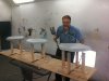
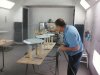
My brother has an auto glass company that does replacement work at several local collision shops. He was able to get use of the paint booth after hours at local Body Shop. This first visit is for just for applying the PPG epoxy automotive primer, which needs to put on in several heavy coats because the MDF really sucks it up. Later, everything will have to be wet sanded out prior to the finish coat being applied.

Here are a couple of shot’s of Darryl applying one of the final coats.
Piano Black  Finish 004.jpg

Piano Black  Finish 008.jpg


In this picture he’s applying what is called a "tracer coat" of black paint from a spray can. A tracer coat is really just a fine coat put on a primered surface before sanding to act as a guide when removing material.
Piano Black  Finish 011.jpg


Here is one of the fluted sidepieces ready for sanding. Notice the black tracer coat.
Piano Black  Finish 020.jpg


I'm using a 400-grit paper wet with a ¼" x 1-1/2" wood dowel to sand down the inside of the flutes.

Basically you sand using water as a lubricant and as a means to keep your paper from clogging by periodically
rinsing it in small tray or bucket of water. You sand until the tracer coat is gone and being very careful not to "burn through" the primer coat exposing the MDF.

I forgot how tedious this can be. I spent approximately 1-1/2 to 2 hours per piecePiano Black  Finish 018.jpg

After the flutes are done, I work on the flat area.
Piano Black  Finish 019.jpg


This picture shows the piece after the flutes and flat areas are done. Notice the fine line where the tracer coat is still left on the small radiuses. This is then sanded lightly by hand because of the risk of burn through. Always leave the edges for last.
Piano Black  Finish 024.jpg


Finished piece.
Piano Black  Finish 025.jpg


Next up is one of the bases. These pieces are easier because they’re not as intricate as the tops.

Piano Black  Finish 030.jpg

Piano Black  Finish 032.jpg
 
Last edited:
Then one of the tops.
Piano Black Finish 041.jpg


This picture is a close up of the flat surface partially sanded. Notice how the trace coat fades out the more you sand. What you’re seeing is that the black remains in the low areas in the primer. When it’s completely gone, you have a smooth surface void of any orange peel.
Piano Black  Finish 039.jpg


Some of the completed pieces.
Piano Black Finish 053.jpg

In between waiting to get back into the spray booth, I finished up on installing the grill cloth.

This is the original OEM cloth from Trend Tex. It was used on the later TimeFrame, CX, and KX speakers. You would think that black is black, but a few years ago when I was replacing the grill cloth on my original TW7’s, I purchase black grill cloth from two different sources and could not get a good match. They both looked bad against the piano black finish on the tops and fluted sidepieces. Checking back with Steve, he remembered who the original supplier was. I found they were willing to sell to me direct so I bought 17 yards and have used it on all my projects.

This photo is with the grill cloth pulled over the entire speaker and gathered loosely at the top. This is the right speaker, notice the seam runs about 5/8" from the back corner on the left.
Grill Cloth 007.jpg


After that, I pulled the excess material down and taped of the area I didn’t want to get the adhesive spray on. The factory would not have done this and would have just sprayed the outer edge.Grill Cloth 023.jpg


After spraying the edges with 3M Super 77 Multipurpose Adhesive, I pulled the cloth back over the top and stretch it out as I worked it into the adhesive.
Grill Cloth 022.jpg

From there, it’s just a matter of trimming the excess with a razor blade and removing the masking tape.
Grill Cloth 011.jpg


With the speaker turned upside down and the bottom finished, the terminal cups openings need to be cut out.
Grill Cloth 012.jpg


Here they are completed. The opening for the port tube is cut out but the tube is not installed yet.Grill Cloth 030.jpg


Here's a comparison with one speaker's grill cloth done. Notice the Mod-ezz fasteners installed to hold the black top caps on.
Grill Cloth 015.jpg
 
Last edited:
Lastly, the two speakers trimmed out except for the piano black tops, bases, and fluted sidepieces.

Before:
Cabinet Build 187.jpg

After:
Grill Cloth 028.jpg


As I mentioned before, the trim pieces are painted and need to be wet sanded and polished. Before I started sanding, I fitted the spikes to the bases. The originals used a rubber insert that metal spikes would be inserted into. This was a nice feature because if you wanted to have the speakers on a surface such as hardwood or ceramic without the spikes, the rubber inserts would contact the floor and not damage it. Since mine were to be used on a carpeted floor, I opted to replace the rubber inserts with threaded metal inserts so I could use threaded spikes and adjust the tilt of the speakers and secure them with a looking nut.


This is the original rubber insert, the same one that was used to hold the grills on the later CX series speakers.
Trim 041.jpg


Comparison between the rubber and threaded metal insert.
Trim 043.jpg


Close-up of the threaded adjustable metal spike with locking nut
Trim 026.jpg


All the spikes mounted.
Trim 027.jpg
 
Last edited:
The final sanding begins.

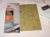
While the paint finish is nice as is, there is always a certain amount of “orange peel” on the surface. Look at any new car finish, it’s the same. To make it look like a furniture grade of polished lacquer, it needs to be wet sanded flat and then polished. To wet sand I use a 2000-grit paper that’s soaked in water and backed with a small hard foam pad. This will level the orange peel out and leave a perfectly flat surface that once polished will look almost as smooth as glass. Normally after using the 2000 grit paper, you would go right to a liquid compound product but I’m trying 3M Trizact 3000-grit foam backed product first. It will reduce the fine scratches left with the 2000 grit so there will be less work with the compound. We’ll see.
Trim 035.jpg

Here’s some photos showing a comparison of the paint showing the slight “orange peel” and one of the bases after sanding. Remember that it’s the sanded clear coat finish that you see, the black is underneath and not touched. The clear will give it the extra depth when polished.
Trim 010.jpg
Trim 015.jpg

Trim 012.jpg

Trim 014.jpg


This next set of photos are of one of the fluted side pieces from start to finish showing the wet sanding and polishing steps.


Trim 052.jpg
This is the piece as it came out of the paint booth; you can see the slight orange peel noticeable in the reflection.


Trim 087.jpg
Then after wet sanding with 1500 grit using a backing pad, then sanding with 2000 then 3000 without a backing pad.


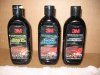
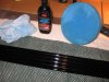
I’m using 3M “Paint Restoration System” which is used in three steps. The first two are compounds and the last a wax. Each has it’s own color coordinated foam buffing pad to use with a DA or orbital buffer. I use a color coordinated micro-fiber cloth to hand rub inside the flute recesses.
Trim 090.jpg


Trim 088.jpg
Step one removes the sanding scratches left from the 3000 3M Trizact.


Trim 109.jpg
Step two removes the very fine scratches left from step one
 
Last edited:
Back
Top Bottom