

You are using an out of date browser. It may not display this or other websites correctly.
You should upgrade or use an alternative browser.
You should upgrade or use an alternative browser.
Dennis Murphy Pioneer SP-BS22-LR DIY Modifications
- Thread starter MCM_Fan
- Start date

Nate27
New Member
I'm using a 1.5h air core inductor in place of the iron core and single .5 air core . Further reading has me wondering how the increased DCR will effect the design. From what I've gathered it can effect sensitivity and qts. 
Edit. Some good reading that comes to the conclusion it doesn't matter between the iron core and air core. So I've probably wasted money on it. https://hificompass.com/en/projects/experiment/test-couple-iron-core-inductors
Edit. Some good reading that comes to the conclusion it doesn't matter between the iron core and air core. So I've probably wasted money on it. https://hificompass.com/en/projects/experiment/test-couple-iron-core-inductors
Last edited:
Hi folks, I figured I would give this a go after using these speakers for six years.
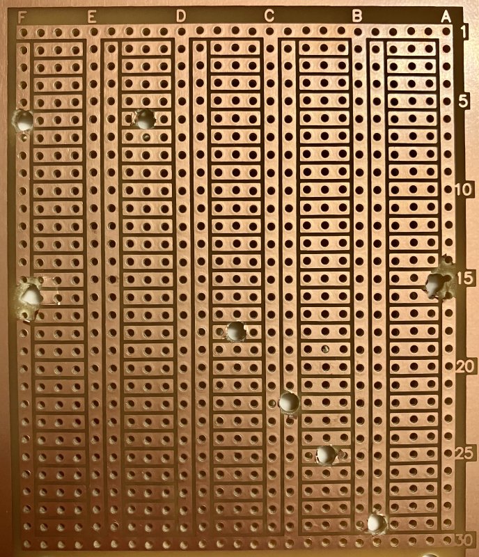
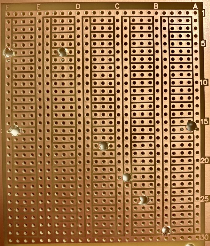
I decided to drill the holes in the board before doing anything else, so that if I messed up that step then at least I haven’t taken the speakers apart yet. I don’t have a drill press so I did it freehand and it came out a bit messier than I had hoped. I wonder if someone can look at these photos and determine if there might be any issues before moving forward? Just wondering if I should proceed or order a couple more boards to try again.
I know I’ll have to install a ground trace jumper wire on of one of the boards since I foolishly drilled the trickiest hole first. After that one, I decided to drill copper-side-up and that seemed to give me cleaner and more precise holes.

MCM_Fan
AK Subscriber
Hi folks, I figured I would give this a go after using these speakers for six years.
I decided to drill the holes in the board before doing anything else, so that if I messed up that step then at least I haven’t taken the speakers apart yet. I don’t have a drill press so I did it freehand and it came out a bit messier than I had hoped. I wonder if someone can look at these photos and determine if there might be any issues before moving forward? Just wondering if I should proceed or order a couple more boards to try again.
I know I’ll have to install a ground trace jumper wire on of one of the boards since I foolishly drilled the trickiest hole first. After that one, I decided to drill copper-side-up and that seemed to give me cleaner and more precise holes.
As noted, on the first board you completely wiped out the ground trace at location A15. Not a big deal, just install a jumper wire between locations A13 and A17 and you should be good to go. The second board looks much better. No jumper required. No need to order more boards.
As noted, on the first board you completely wiped out the ground trace at location A15. Not a big deal, just install a jumper wire between locations A13 and A17 and you should be good to go. The second board looks much better. No jumper required. No need to order more boards.
Thanks, yeah I really did a number on that one. Hopefully the rest goes more smoothly.
anotherone
New Member
After that one, I decided to drill copper-side-up and that seemed to give me cleaner and more precise holes.
This tip should be added to the instructions. I hit the same issue, but by dumb luck the first hole I chose to drill was on the other side, so I didn't have to make any repairs. One bad hole, drilled the rest copper side up and everything came out nicely. Maybe that's a rookie mistake.
I wasn't able to source an original Radio Shack board (especially in Europe, where getting hold of something Radio Shack would be as hard as finding a pair of BS22s), but there's a company in Poland making clones of them, which meant I could follow the instructions to the letter instead of having to figure out how to map the circuit on to a different project board.
Oh, and Digi-key didn't pack the tweeters properly. I had to suck the dome of one of them back into shape. Seems no harm done though.
MCM_Fan, my ears thank you and Dennis for your efforts. That's one more successful DIY pair of AAMs, in case anyone's counting.
After 10 years, you finally got to it?This tip should be added to the instructions. I hit the same issue, but by dumb luck the first hole I chose to drill was on the other side, so I didn't have to make any repairs. One bad hole, drilled the rest copper side up and everything came out nicely. Maybe that's a rookie mistake.
I wasn't able to source an original Radio Shack board (especially in Europe, where getting hold of something Radio Shack would be as hard as finding a pair of BS22s), but there's a company in Poland making clones of them, which meant I could follow the instructions to the letter instead of having to figure out how to map the circuit on to a different project board.
Oh, and Digi-key didn't pack the tweeters properly. I had to suck the dome of one of them back into shape. Seems no harm done though.
MCM_Fan, my ears thank you and Dennis for your efforts. That's one more successful DIY pair of AAMs, in case anyone's counting.
HighFutility
New Member
Hey, I was wondering if anyone could help with the modification. I want to start out by saying this is my first time working with crossovers. I have no experience. I am also relatively new to soldering. The only time I have used a soldering gun is for my DIY subwoofers, but that is very straightforward.
I botched the original PCB and am working with a piece of MDF.
Here's where I am at so far.
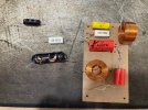
I will most likely glue everything down.
Can I mount the one mH iron core along with the resistor and capacitor on the other side of the mdf? Or will the air core interfere with the Ironcore through the mdf>?
If none of what I am asking makes sense, it's because I am green.
Thanks in advance.
I botched the original PCB and am working with a piece of MDF.
Here's where I am at so far.
I will most likely glue everything down.
Can I mount the one mH iron core along with the resistor and capacitor on the other side of the mdf? Or will the air core interfere with the Ironcore through the mdf>?
If none of what I am asking makes sense, it's because I am green.
Thanks in advance.
HighFutility
New Member
Hey, Thank you for your reply. Just for clarification, when you say at the "bottom under,." Are you referring toYou should be fine if you keep the iron core down at the bottom under L2. The rule of thumb is 3 inches, but since these are in series to make an effective 1.5mH, it's not a problem.

Or like this

Both options would be on the other side of the MDF. I have read "down at the bottom under L2" too many times, and my OCD is nitpicking the verbiage.

HighFutility
New Member
Thank you for your work.Either one is fine. I just measured a 1.5mH steel-core and then placed a .40mH air-core directly on top of it. I saw no difference on my cheap little LCR meter.
View attachment 3133214

HighFutility
New Member
Okay, so I soldered and zip-tied a few things down. I feel like I am in the home stretch. Apologies in advance for what looks like a hack job, most likely because it is, it's my first time. I see the appeal of using a PCB board.
I went ahead and connected the positive from the binding posts to C3 2.2UF as well as L2 O.5MH. I drilled a hole and shot the cable up.
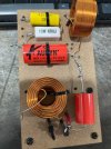
My next question is about connecting all the grounds together. Again, I see the benefit of a PCB with pathways instead of creating them with wires.
Is the woofer W+ going to be soldered at the same junction as the C1 & L1 and W- going to R1, -binding post, L3, C2, TW-? Do you just tie up all the grounds together?
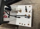

I went ahead and connected the positive from the binding posts to C3 2.2UF as well as L2 O.5MH. I drilled a hole and shot the cable up.
My next question is about connecting all the grounds together. Again, I see the benefit of a PCB with pathways instead of creating them with wires.
Is the woofer W+ going to be soldered at the same junction as the C1 & L1 and W- going to R1, -binding post, L3, C2, TW-? Do you just tie up all the grounds together?

JSMATT
Member
One thought concerns the use of the zip ties for anchoring your various components. I have had some zip ties purchased in the past 10 years that degraded really quickly in room temp conditions. Just an observation!Okay, so I soldered and zip-tied a few things down. I feel like I am in the home stretch. Apologies in advance for what looks like a hack job, most likely because it is, it's my first time. I see the appeal of using a PCB board.
I went ahead and connected the positive from the binding posts to C3 2.2UF as well as L2 O.5MH. I drilled a hole and shot the cable up.
View attachment 3134676
My next question is about connecting all the grounds together. Again, I see the benefit of a PCB with pathways instead of creating them with wires.
Is the woofer W+ going to be soldered at the same junction as the C1 & L1 and W- going to R1, -binding post, L3, C2, TW-? Do you just tie up all the grounds together?
View attachment 3134678View attachment 3134689

earplay2
New Member
I was thinking about doing the Murphy mods on my SP-BS22-LRs, but when I priced out the parts list I found this on Parts Express:
Jantzen Audio 2.0mH 15 AWG Air Core Inductor Crossover Coil $38.12.
With the discount for four, these inductors come to $146.72 + tax.
Is there a significantly less expensive source for these inductors?
Jantzen Audio 2.0mH 15 AWG Air Core Inductor Crossover Coil $38.12.
With the discount for four, these inductors come to $146.72 + tax.
Is there a significantly less expensive source for these inductors?

You're in luck. There are no 2.0mH inductors in this design. It calls for (x4) 0.50mH 20 AWG. You can use the Dayton version that are only $4.39 each.
https://www.parts-express.com/Dayto...AWG-Air-Core-Inductor-Coil-257-036?quantity=1
https://www.parts-express.com/Dayto...AWG-Air-Core-Inductor-Coil-257-036?quantity=1