• The move to the new server is done. There are some software and database maintenance updates in process. This has us passing the hat around to help out. We appreciate any donations. Seriously, even a dollar helps. The payment page may be found here - https://www.audiokarma.org/support.html

Denon AVR-X1200W repair help

Gl-dunk-27

New Member
Hello all, I am trying to repair my said AVR after it started going into protection blinky red. Have some knowledge of electronics (college courses in the 90s :)) and do solder here and there.

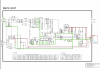
Service manual for this AVR is here.

So far, successfully replaced 7912 voltage regulator in the Regulator board, after which it did come out of protection and proceeded showing the receiver mode, tried changing to last mode and then turned off again. Did some check and turned out that a zener diode on digital pcb was short with some resistor (long leg bent over the resister leg and shorted). Replaced that with one ordered from Amazon. Also, removed some caps and resoldered back after testing.

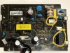
Now, it shows up that it powers up and goes solid white led (always been white instead of green, maybe previous owner diy). However, display on panel is blank and no relay click.

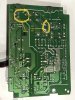
Have tried reflowing all solders, checked almost all components, relay and voltages. Found a few odd things but need someone’s help to identify if my understanding is wrong. Adding images. Here we go:
  1. Even when not powered, seeing 5.2V at the output of this SMPS board into the regulator board. Is this right?
  2. In above case, relay has 120V AC across it. Is this right behavior or something is short?
  3. Power Relay is not clicking when in circuit even when it has 120V across it. Why?
  4. Transformer input resistance (blue black wire) seems to be just 1.5ohms and 4.5 for some output wires, don’t remember which one. Voltage across is 0, so 120V comes across to relay, is this right behavior? Transformer probably is alright but not sure.
Can any experts help me to troubleshoot this?
 

Attachments

  • 108E9361-565C-455D-811F-D55E06F85814.jpeg
    108E9361-565C-455D-811F-D55E06F85814.jpeg
    144.6 KB · Views: 20
  • 0B1BD535-778D-4C0C-9BCE-597763F6424E.jpeg
    0B1BD535-778D-4C0C-9BCE-597763F6424E.jpeg
    138.4 KB · Views: 19
Register to hide this ad
Hello. AVR receivers are very hard to fix, that's why I don't receive this units anymore for repair.

5.2V present is normal. At BN601 (SMPS output), you'll have 5.2V going to the unit, and at the "MAINPOWER" pin (on that same connector) a signal should be present when you power ON the unit, to bias transistor Q603 (near the power relay), shunting the relay coil to ground and closing the circuit (engaging the relay).

Don't "jump" the relay, since some protection circuit could be blocking the "MAINPOWER" signal due to some fail, protecting the unit.

I'd 1st check if some voltage is present at the Mainpower pin (Q603 base) when you press the power button.

120 V across the relay contacts (when the relay is open) is also normal.
 
Thank you, elnado! I will definitely check it out. Meanwhile, I was looking at the adjustable regulator and optocoupler values (after reading up on it). If they were not working properly, what should I be expecting at the output of these ICs? Schematics don’t seem to tell me that level of detail. Will find out.
 
Thank you, elnado! I will definitely check it out. Meanwhile, I was looking at the adjustable regulator and optocoupler values (after reading up on it). If they were not working properly, what should I be expecting at the output of these ICs? Schematics don’t seem to tell me that level of detail. Will find out.
Can you point me to the right page on the Service manual?
 
Voltage at MainPower is 5.2 same as pins 1&2, both in on and off state of receiver. Volts at Kia2431AP is 3.96 at Ka, 0 at Anode and 1.18 at Ref. Volts at Optocoupler is 5.06 at pin 1, 3.96 at adjacent pin and -0.7 at both opposite pins, when in on state of receiver (did not measure in off state). Big Power transformer was giving out 34.9V for W-W pins, 5.3V for O-O pins, 17V for Blue-Black, 42V for Red-Black and 16.4V for Yellow-Black. Individual components have checked out ok. Any ideas?
 
Voltaje at main power pin should change from off to on state. Did you check Q603? A shorted transistor could send 5V back to the main power pin. I can check the schematic later.

I understand the power relay was not engaging, but you are posting voltages from the main transformer, which shouldn't be energyzed if that relay is open.

Can you check the Relay coil for dc resistance, or try to power the relay with some external 5V supply? UNIT UNPLUGGED FROM THE ELECTRICITY.
 
Thanks! sorry for the confusion. I checked the BIG transformer (CLT5U057ZU) after disconnecting it from everything and gave 120V AC input to see if it is giving voltages at output. It was working as far as I could tell. I also tested the relay independently after de-soldering. It engaged at 27V but did not engage from 1-12V. I do not have a variable power source at the moment, so couldn't determine at what voltage it starts engaging. But yes, the transformer is not energizing when the relay is open.

I remember relay coil was around 100Ohms when I tested earlier, will check that again later today. I did not think about testing individual smd components. Will check the q6003 also later today. Thanks!
 
Last edited:
Thanks! sorry for the confusion. I checked the BIG transformer (CLT5U057ZU) after disconnecting it from everything and gave 120V AC input to see if it is giving voltages at output. It was working as far as I could tell. I also tested the relay independently after de-soldering. It engaged at 27V but did not engage from 1-12V. I do not have a variable power source at the moment, so couldn't determine at what voltage it starts engaging. But yes, the transformer is not energizing when the relay is open.

I remember relay coil was around 100Ohms when I tested earlier, will check that again later today. I did not think about testing individual smd components. Will check the q6003 also later today. Thanks!

Hello. Page 158 of the PDF: the relay is a DC5V relay, it should engage with 5V DC. If it doesn't, replace the relay. That doesn't discard other problems, but the relay is energized with 5.2V (red dashed line on the schematic). You need a relay that actuates when fed by 5V DC.
 
Hi Elnado, thanks for that! I was wondering about that but the relay on its box says 30VDC. See attachment, hence thought otherwise. But I will try. Will order now and try once it arrives.
Update on relay testing: I desoldered again and tested. This time, it seems to be engaging at 3.1V and pin 2&3 have continuity when engaged. Resistance is 102 ohms between pin 1&4 when disconnected.
 

Attachments

  • AF934E4F-5C68-4B30-9A21-21457B0EC5B1.jpeg
    AF934E4F-5C68-4B30-9A21-21457B0EC5B1.jpeg
    78.2 KB · Views: 9
Last edited:
3.1V is OK for a 5 V relay.
The numbers you see on the relay are the current ratings for the contacts: 10A @ 250VAC, and 5A @ 30VDC.

But it seems the relay is fine. Time to see why the circuit is not working.
It could be: Q603 not working, so not closing the circuit to ground. Or, Q603 not biased (check R6024 and R6025)
Diode D6009 shorted, so shunting the voltage to ground, voltage going through the shorted diode instead of the relay coil.

Or... Unit into protection not sending the power signal...

The relay circuit is very simple: you have 5.2V reaching the relay coil, the other end of that coil is connected to Q603 which acts as a switch closing the circuit to ground when it receives a signal at the Base, coming from the Main Power pin. That's why I'd expect 0V when off, and 5V when ON at that pin.

A tip to desolder SMT devices: to work with 2 soldering irons. You add a bit of fresh solder at both sides, and with 2 soldering irons you heat both sides at the same time. Anyway in a small transistor just adding a large blob of solder will allow to remove it (if needed)
 
Last edited:
Thanks for the detailed info. I was able to desolder the transistor Q6003 and measure the continuity. The base to right pin (connected to R6024,R60025) is showing 65 as opposed to usual 600-720 that I see with diodes. The base to other pin is open. This is for true if the polarities are switched. The R6024 measures 10.09K ohms and R6025 measures 4.68K ohms. Also, AFAIR, I was not seeing 5.2V across the coil earlier when I had measured.

The cap C6018 has though 5.2V correctly, so I am guess the open transistor is the issue then?

D6009 shows 109 when in circuit but when desoldered and checked showed proper 620 as one would expect.

D6013 Schotky Diode pair BQ30T (PNP) has 180 from both ends to center pin. Wondering if this is ok as typical diodes would be 600~750 AFAIK.
 
Last edited:
You won't have voltage across the relay coil until the circuit is closed and current flows. With an open circuit, you'll have 5.2V at both ends of the coil (referred to ground)

Transistor BASE is the pin connected to R6024. Emitter is the pin connected to ground. Collector is connected to the relay coil.

In any case, a voltage drop of 65 (and not 650) is not normal in any of the junctions. So, if you doubt of that transistor, just fit a new one. Any regular NPN will work, the original part is a 50V 200mA 150mW transistor, you can solder a regular TO92 if you follow the right pinout. (I've done that many many times)

A schotky diode is probably a low voltage drop type. I'd consider it OK. You can check the datasheet if you want.
 
Thanks for the info! You guessed it right. Base to emitter is open. Will order new one tomorrow, maybe a TO92, and test again. Will be careful about the appropriate pins. Thanks!!
 
Some progress now. I picked up 2N3904 transistor from Microcenter (luckily they had this) and have soldered it in place of the 2SC3205 transistor. Now, I don’t see the main power at 5.2V in both on/off cases. Tell me if my understanding is wrong: the main power 5.2V forward biases the Q6003 which then makes current flow from collector into emitter thus engaging the relay. But confused about the main power. When turned on, where does it get the 5.2V from since the main power seems to be connected only to base of Q6003 through R6025? For the Schotky barrier diode, now I see 5.2V only at pin#2 i.e. at the common cathode. Both other pins are at 0 even when turned on. Also, I see pin3 and pin1 connected only to transformer pins 10&11 respectively on secondary side. Are the volts correct there?
 
Last edited:
Hello.

The 5.2V from pins 1 and 2 on connector BN601 go to the main board (CN741), and some microprocessor on control circuit will send the 5,2V (or any control voltage) back to the SMPS board through BN601 pin 6 (mainpower), engaging the relay.

The 5.2V supply (red line) is a stand-by voltage , it's always present when the unit is plugged to the main voltage.

If you don't see that 5V signal at the "mainpower" pin, something is happening, it could be the protection circuit works fine and is detecting a problem, it could be the protection circuit needs to be reset (some amplifiers refuse to start after some failure until you reset the protection in some way, sometimes pressing some keys at the same time while powering ON), or it could be the protection circuit not working as expected.
At page 107, pin 127 on the main IC751 is the mainpower signal. Ig goes from that pin almost straight to the SMPS board, through one inductor, L7429, at page 106, top right. If that inductor is open, the power signal can't reach the SMPS board. If the inductor is OK and connectors and soldering are OK, some major problem is stopping IC751 to send the signal, it could be the IC itself. Check you have 3.3V DC feeding that IC (IC748 at page 106, a 3.3V regulator fed by the 5,2V) (find some point at that board to check it without shorting the IC pins)

Please read pages 74 and 19 of the service manual.

avrx1200w_page119.png
 

Attachments

Last edited:
Thank you for the explanation. Earlier when I was checking (before the transistor fix), I was not seeing voltages in CN823 and CN754 and also nothing in CN762. My thinking was since Big transformer is not giving AC into the regulator PCB via CN302, that might be normal. Is that so though? I checked the L7421 inductor and it is showing continuity. Also, the IC748 is not connected or empty. See attached image. And you are talking about 3.3V via the CN302?

On page 74, in one of the steps it says disconnect BN501 but I can disconnect CN761 to have same effect, right? Should I be expecting be volts in CN823, CN754 and in CN762 even when relay is not engaging?
 

Attachments

  • ABF91A24-47FB-4B74-9D3C-465B51A2A429.jpeg
    ABF91A24-47FB-4B74-9D3C-465B51A2A429.jpeg
    154.8 KB · Views: 6
Last edited:
I'll check the schematics later. But by now the only voltage present in the unit will be the 5.2V from the SMPS and some 3.3V powered by those 5.2V. The main processor IC751 at page 107 needs power. Check the schematic against the PCB and check it's receiving 3.3V on that board. If that IC is powered, it should send the mainpower signal all the way back to the SMPS board.
 
I see the schematic says "OPEN" right beside IC748, it seems it's not fit. Anyway, check the "MCU PART" board, page 107, the processor must be energized with 3.3V coming from some regulator. Check pins labeled "MCU 3.3V".

Red dashed lines indicate "standby power", so I'd expect all those voltages present when the unit is OFF, in standby mode.
 
Thank you elnaldo! Will test out those pins today. Anything to also check in the “Main PCB” underneath the “Digital PCB”, not sure I can check though? (Names are from their manual)
 
Back
Top Bottom