You are using an out of date browser. It may not display this or other websites correctly.
You should upgrade or use an alternative browser.
You should upgrade or use an alternative browser.
Denon PMA-1560 unobtanium MOSFETs

Samuel36100
New Member
Samuel36100
New Member
Samuel36100
New Member
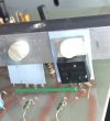
I'm not really satisfied for heatsink. I should have put transistor in triangular position, for more stability. And put an aluminium plate in the center.
I would do that again, one day.....
I would do that again, one day.....
Samuel36100
New Member
I replaced the originals power transistors, 2SA1492 and 2SC3856 by 2SC5200 and 2SA1943. It's a good choice or not ?
(I had these, at this moment)
(I had these, at this moment)

They are fine. Pretty much the same specs.It's a good choice or not?
I will also try to make this change. I noticed in the schematic (PDF) that you forgot to mention that capacitors C526 and C528 also need to be removed, and that resistors R550 and R552 must be replaced with jumpers. Is that correct?Wow. Just wow. What a rollercoaster ride. Whatever I did made no difference. Either it started to oscillate without bias or it started to oscillate with bias. This amp is one temperamental beast. But I got it tamed and have a fix for those unobtanium MOSFETs. See the attached amplifier module schematic. Finally it is stable:
View attachment 1877006
I removed five capacitors, two transistors, a resistor and two diodes. I replaced several resistors and one capacitor. It's clear the Japanese engineers ran into the same issues I did only they didn't have the tools I have available. Mainly LTSpice. The latest version also attached (ZIP).
Fun fact: while it took me weeks to find the solution it only took me minutes to fix the second amp...
Yes. The schematic is leading, not the text. I must have overlooked that six years agoIs that correct?

I worked on several Revoxes and think they are more nightmarish than most Japanese gear. This Denon is an exception and there are many more but still...Unlike the Revox units, though, the Japanese ones are a total nightmare.
Today I received the Transistors MJE15034 and MJE15035.
Your photo shows that these transistors were installed directly as-is, however, since the middle pin of the transistor is the collector and according to the schematic it needs to connect to the point where the MOSFET's drain was originally connected, wouldn't the collector and emitter pins need to be swapped? Did you rewire the PCB so that you didn't have to twist the leads during installation?
Your photo shows that these transistors were installed directly as-is, however, since the middle pin of the transistor is the collector and according to the schematic it needs to connect to the point where the MOSFET's drain was originally connected, wouldn't the collector and emitter pins need to be swapped? Did you rewire the PCB so that you didn't have to twist the leads during installation?
I must have. I did not make any pics from the copper side, this is what I have:Did you rewire the PCB so that you didn't have to twist the leads during installation?
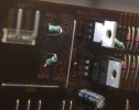
I have now opted for a minimally invasive approach: I disconnected the source connections after resistors R552 and R550, drilled a hole there, and soldered in a jumper; additionally, I soldered a jumper into the base and collector holes for TR524 and TR526.