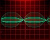
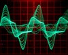
This is a modded Denon PMA-700V with a digital input. I had loaned it to my neighbor but to my chagrin it came back with blown output transistors (2SA1962/C5242). This was probably caused by a dry joint at the collector of TR505 but I am not sure. To prevent this from happening again I wanted to add a current limiter across the emitter output resistors R571 and R569. The output stage only has single transistors now (TR513/5) so adding current sense transistors across the resistors that pull the bases of TR503/5 down should work. In a fashion, they do. When they trigger positive the output voltage shoots negative and then positive again:
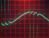
The amplitude is 10 V/div and the time 0.2 ms/div. The current limiter seems to trigger at 15 V which in this case is at V=I/R=15/1.25=12 A. The load here is that 1.25 Ohm. The power drawn from the mains is 200 W.
What happens is that the voltage amp driving the current amp goes berzerk as it tries to get more voltage which the current amp refuses to provide. The question is: how do I tame it so the current limit works as it should? Looks like the engineers at Denon were unable to get this working so they just left it out. After all, Denon's configuration is unusual.
This is the schematic:
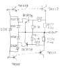
It is a standard current limiter as used in many other amps. The 4.7k resistors reduce the sensitivity of the BC847B/857B transistors at higher voltages so they only act at short circuit.
This is the module:
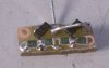
and here it is installed:
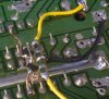
Right now I'm at a loss how not to upset the voltage amplifier (attached to the left of the snippet from the schematic) while still getting current limit.
The amplitude is 10 V/div and the time 0.2 ms/div. The current limiter seems to trigger at 15 V which in this case is at V=I/R=15/1.25=12 A. The load here is that 1.25 Ohm. The power drawn from the mains is 200 W.
What happens is that the voltage amp driving the current amp goes berzerk as it tries to get more voltage which the current amp refuses to provide. The question is: how do I tame it so the current limit works as it should? Looks like the engineers at Denon were unable to get this working so they just left it out. After all, Denon's configuration is unusual.
This is the schematic:
It is a standard current limiter as used in many other amps. The 4.7k resistors reduce the sensitivity of the BC847B/857B transistors at higher voltages so they only act at short circuit.
This is the module:
and here it is installed:
Right now I'm at a loss how not to upset the voltage amplifier (attached to the left of the snippet from the schematic) while still getting current limit.