• The move to the new server is done. There are some software and database maintenance updates in process. This has us passing the hat around to help out. We appreciate any donations. Seriously, even a dollar helps. The payment page may be found here - https://www.audiokarma.org/support.html

Denon POA 6600 Thread

Bratwurst7s

In The Frying Pan
Subscriber
edit 06 April 2024:
This will be the oddest start to a dedicated amp thread that I have ever made. The thread originally had the thread title "Replace M5218P Op-amp with NJM5532? Yes, No?" and was intended to be nothing more than a look into an op-amp sub.
Once dr audio stepped in to help the thread kinda mutated into an amp thread. I had always planned on starting a thread dedicated to the Denon POA 6600, so it is just easier to rename this one than start a new thread.
In any case, in some ways the thread will actually start on post #50 on page 3. :biggrin:
Consider everything up until that point as a preamble.
_____________________________________________________________________________________________________________________________________________________________________________

I have some Denon POA 6600 first generation mono amps, not the later "A" ones with the optocoupler biasing arrangement but rather using a M5218P op-amp.

I am unsure if the op-amp is good and do not know how to test them. I do have a number of NJM5532 op-amps on hand.
Before I worry about having to take this thing apart again I would prefer to replace the 5218. I am thinking that a 5532 should work but am unsure.

Note that if I was unclear, the op-amp is not working directly with the signal, it is in the output biasing section. Thinking that an ultramodern high slew rate part would be overkill, although the 5532 in itself is faster than the 5218. I don't want to introduce oscillation :)biggrin:), just reliability.

Thanks in advance for any informed responses.

Cheers,
James

edit: Actually, I am thinking that installing a very high slew rate op-amp would be dangerous and risk oscillation. I would actually just buy a new M5218 if they could be found. I searched for a "near exact" sub but didn't find much of any info.

edit2: I should have attached the data sheets here. Done.
 

Attachments

Last edited:
Register to hide this ad
I'll have a look at the schematic. I am not aware of Denon using an opamp in the biasing scheme. What I have seen is they use it as a voltage amp or feed forward. I have seen opamps used in a servo circuit to cancel DC. I bet that is what this is used for, and if so, a 5532 will work because there is a feedback circuit with a low pass filter anyway. I'll try to look at the schematic tomorrow, it's bed time.
 
I'll have a look at the schematic. I am not aware of Denon using an opamp in the biasing scheme. What I have seen is they use it as a voltage amp or feed forward. I have seen opamps used in a servo circuit to cancel DC. I bet that is what this is used for, and if so, a 5532 will work because there is a feedback circuit with a low pass filter anyway. I'll try to look at the schematic tomorrow, it's bed time.
Thanks for replying. I know that you have extensive knowledge so I am grateful that you are taking the time to look. :thumbsup:

When you do get to the schematic, D510 (5V zener) was shorted. Every other part in the entire board has been tested except for the 2 op-amps because I have no idea how to test them. That zener is the only part in the entire amp that has tested bad.

The amp passed the dim bulb on first start up and came out of protection. But it showed zero mV on the idle current test points and did not respond to adjustment.

James
 
Last edited:
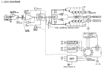
So to start out, have a look at the block diagram below. From this you can see that the opamps are used in the DC Servo and feedback circuits and not in the bias. A2 and A3 appear to be feedback as well. To be continued...
1711131085993.png
 
While I'm waiting for you to do the voltage checks, here is a primer on opamps:
1. An opamp is a device with a non inverting input and an inverting input.
2. If an opamp has no negative feedback around it, it will have extremely high gain. Theoretically it would have infinite gain but it's an imperfect world so the gain is just very high.
3. For an opamp to be useful in audio circuits we need to place negative feedback around it to give it a finite, controllable gain.
4. Feedback around the opamp increases the frequency response as well as reducing the gain. If you connect the output of the opamp to the negative input, this sets the gain of the opamp at X1, or unity gain. It also sets the frequency response at the maximum for that device, the specification for this is Unity Gain Bandwidth.
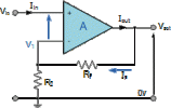
5. To configure the opamp as a non inverting amplifier, it is connected as below:
1711160599828.gif
Rf and R2 form the feedback network and the formula for figuring out the gain is: Av = 1 + (Rf/R2) where Av is voltage gain.
6. When you have negative feedback around an opamp, it puts out a voltage at the output such that the voltage on the + and - inputs are equal. So if you want to check if an opamp is working, look at the + and - inputs. If it has feedback then the input voltages will be within uV of each other. If not, it's probably blown or there is a bad component in the feedback network.
7. An opamp configured as an inverting amplifier has the output signal inverted from the input and is connected like this:
1711161064218.png
The gain of an inverting opamp is calculated by: Av = Rf/R2. If you want to be exact about it, it's Av = -1 X Rf/R2 to show that the output is inverted.
8. When trying a different opamp to try and improve performance, several factors should be taken into consideration:
a. Slew Rate; do you want it higher? Usually yes.
b. Is the replacement unity gain stable? If the circuit is configured for unity gain, the replacement MUST be unity gain stable or it could oscillate.
c. The replacement must be able to tolerate the voltage supplies used. Most will work with +/- 15V but some circuits use higher supply voltages.
d. Distortion and noise should be rated as good or better than the original.
e. Some circuits require a high input impedance and you need an opamp with jfet inputs.
f. Input offset current can be critical in some circuits and you'll have a DC offset on the output if the offset is too high. Remember where I said the 2 inputs should be within a few uV of each other? The input offset current causes the difference between the inputs.
 
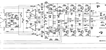
I don't know if this saves any time or not but I went through and measured the voltage points shown on the schematic. I don't have the skills to calculate predicted voltages elsewhere but I can at least do that.

Working from the left of the schematic to the right: Location / Schematic value / Measured value
Plus side of C501 / 15.2v / 15.24v
Anode of D502 / -15.0v / -15.4v
TR503B / 12.8v / 12.87v
Junction of R517, 518,519 / 12.4v / 12.29v
Junction of TR504C, TR523E / 0.59v / 0.584v
Anode of D503 / 0.59v / 0.63v
TR506C / -0.64v / -0.61v
TR507E / -21mV / -20mV
TR506E / -60mV / -61mV
R529,531 / 47.8v / 43.2v
R532, 532 / -47.8v / -43.2v
IC501 pin 8 / 15.1v / 15.17v
IC501 pin 4 / -15.2v / -15.2v
IC501 pin 1 / 43mv / 21mv
Anode of D509 / -0.34v / +0.50v
Cathode of D509 / -0.57v / +0.81v (checked D509 3 times to be sure, read plus voltage there)
IC502 pin 1 / -37mv / +8mv
IC502 pin 7 / -38mv / +10mv (also triple checked, plus voltage here)
 
Last edited:
While I'm waiting for you to do the voltage checks, here is a primer on opamps:
1. An opamp is a device with a non inverting input and an inverting input.
2. If an opamp has no negative feedback around it, it will have extremely high gain. Theoretically it would have infinite gain but it's an imperfect world so the gain is just very high.
3. For an opamp to be useful in audio circuits we need to place negative feedback around it to give it a finite, controllable gain.
4. Feedback around the opamp increases the frequency response as well as reducing the gain. If you connect the output of the opamp to the negative input, this sets the gain of the opamp at X1, or unity gain. It also sets the frequency response at the maximum for that device, the specification for this is Unity Gain Bandwidth.
5. To configure the opamp as a non inverting amplifier, it is connected as below:
View attachment 3155677
Rf and R2 form the feedback network and the formula for figuring out the gain is: Av = 1 + (Rf/R2) where Av is voltage gain.
6. When you have negative feedback around an opamp, it puts out a voltage at the output such that the voltage on the + and - inputs are equal. So if you want to check if an opamp is working, look at the + and - inputs. If it has feedback then the input voltages will be within uV of each other. If not, it's probably blown or there is a bad component in the feedback network.
7. An opamp configured as an inverting amplifier has the output signal inverted from the input and is connected like this:
View attachment 3155681
The gain of an inverting opamp is calculated by: Av = Rf/R2. If you want to be exact about it, it's Av = -1 X Rf/R2 to show that the output is inverted.
8. When trying a different opamp to try and improve performance, several factors should be taken into consideration:
a. Slew Rate; do you want it higher? Usually yes.
b. Is the replacement unity gain stable? If the circuit is configured for unity gain, the replacement MUST be unity gain stable or it could oscillate.
c. The replacement must be able to tolerate the voltage supplies used. Most will work with +/- 15V but some circuits use higher supply voltages.
d. Distortion and noise should be rated as good or better than the original.
e. Some circuits require a high input impedance and you need an opamp with jfet inputs.
f. Input offset current can be critical in some circuits and you'll have a DC offset on the output if the offset is too high. Remember where I said the 2 inputs should be within a few uV of each other? The input offset current causes the difference between the inputs.

I am working on digesting this.
Considering your point 8e, would this explain why IC501 NJM082BD is a dual Jfet?
 
Some background on what has gone on before this point.

I bought 2 of these amps, supposedly in good working order, in August 2023. Both amps passed a dim bulb test. Both amps came out of protection.
The 1st amp that I put on the bench (I will ID it as Amp1) I was able to adjust the idle current to the stated 8mV after it warmed up, it was at 7mV, so, pretty good.
The second amp (Amp2) is the one that we are dealing with here.

I discussed it with my foreman at work and we made a list of suspect items, all in the idle current adjustment area. I checked the stated schematic voltages, noted incorrect results at both opamps.
I noticed at that time that someone had been in the amp before me. R555 and R559 had both been replaced with large non-fusible 100 ohm resistors. R559 is supposed to be 470 ohms and both 1/4w fusible.
Someone had resoldered Tr509, Tr510 Tr511, Tr512, Tr551 and Tr525, as well as C511 and C544.

Every part in the idle current section was removed, tested (except for the op-amp) and every part tested good.

At that point since I couldn't calculate what all of the voltages were supposed to be I decided to measure a large number of points in Amp1, document them and use that as a basis to co forward.
I got as far as making a list, opening the amp and turning it on. Then, before doing a damn thing, just sitting there letting it warm up while I decided on where to start, R536 burned and smoked.

From that point Amp1 went on a shelf and I did what was most likely a mistake (violates the "fix it first" rule) but I proceded to systematically remove, test, replace or reinstall every part on the board. The only things that I did not check at that time were the zener diodes (didn't know how to test at that point), op-amps and the outputs.

Every single solder point in the entire board was re-soldered.
Every single part tested good.
The old carbon film resistors were not re-installed but were replaced with 1% metal film.
The old "normal" diodes were not re-installed but were replaced with 1N4148.
The MV-1YH diode was not re-installed, was replaced with a 1N4148 and thermal paste.
All small signal transistors were tested and re-installed.
All of the above happened last September.

After that the amp went on a shelf while I worked on a backup solution. I also bought a Peak Atlas DCA75pro and Zen50.

After coming back to the amp last week I tested all of the zener diodes with the Zen50. All measured 0.4v to 0.2v low except for D501 which was shorted.
(replacing D510 cleaned up the voltage at the output of IC501, which previously measured +1.1v instead of +43mV, now it reads low at +21mV)
All of the zeners are now replaced. The HZ-15-2 with 14.8v parts and the HZ-5C-1 with 5v parts, all tested and matched.
The output transistors were removed, tested (all good but with high variance) and replaced with 2SA1962 and 2SC5242.

This is where things stand now.

James
 
Last edited:
Oh, I did not re-install any electrolytic caps, they were all replaced.
I did a thorough inspection of the board for solder bridges etc, inch by inch and also with backlight.
The op-amp position have been socketed and the original op-amps re-installed.

I documented the measured value of each and every original part and have that info on hand.

James
 
While I'm waiting for you to do the voltage checks, here is a primer on opamps:
1. An opamp is a device with a non inverting input and an inverting input.
2. If an opamp has no negative feedback around it, it will have extremely high gain. Theoretically it would have infinite gain but it's an imperfect world so the gain is just very high.
3. For an opamp to be useful in audio circuits we need to place negative feedback around it to give it a finite, controllable gain.
4. Feedback around the opamp increases the frequency response as well as reducing the gain. If you connect the output of the opamp to the negative input, this sets the gain of the opamp at X1, or unity gain. It also sets the frequency response at the maximum for that device, the specification for this is Unity Gain Bandwidth.
5. To configure the opamp as a non inverting amplifier, it is connected as below:
View attachment 3155677
Rf and R2 form the feedback network and the formula for figuring out the gain is: Av = 1 + (Rf/R2) where Av is voltage gain.
6. When you have negative feedback around an opamp, it puts out a voltage at the output such that the voltage on the + and - inputs are equal. So if you want to check if an opamp is working, look at the + and - inputs. If it has feedback then the input voltages will be within uV of each other. If not, it's probably blown or there is a bad component in the feedback network.
7. An opamp configured as an inverting amplifier has the output signal inverted from the input and is connected like this:
View attachment 3155681
The gain of an inverting opamp is calculated by: Av = Rf/R2. If you want to be exact about it, it's Av = -1 X Rf/R2 to show that the output is inverted.
8. When trying a different opamp to try and improve performance, several factors should be taken into consideration:
a. Slew Rate; do you want it higher? Usually yes.
b. Is the replacement unity gain stable? If the circuit is configured for unity gain, the replacement MUST be unity gain stable or it could oscillate.
c. The replacement must be able to tolerate the voltage supplies used. Most will work with +/- 15V but some circuits use higher supply voltages.
d. Distortion and noise should be rated as good or better than the original.
e. Some circuits require a high input impedance and you need an opamp with jfet inputs.
f. Input offset current can be critical in some circuits and you'll have a DC offset on the output if the offset is too high. Remember where I said the 2 inputs should be within a few uV of each other? The input offset current causes the difference between the inputs.
OK, so I see that the IC501 opamp in my unit has a 33pF cap in the feedback loop to pin2 (-) rather than a resistor. Or am I seeing that wrong? So this opamp is being used differently than the example I am guessing?
 
Lots of information here to wade through. Are you sure you tested TR551? Please retest it using the Diode range on your meter with the power off. Also the diode right below it. I'll try to get back to this later.
 
Ok, I will do that.

Yeah, sorry about the info bomb.
I was planning on eventually starting a dedicated thread on the POA 6600's. Now that there is a buildup of info here I am thinking of just re-naming this thread to "Denon POA 6600 Thread" rather than start over.

TR551 tested at:
hFE = 366
vF = 670mV
I tested it with both my cheap Chinese tester and the DCA75. It is mounted to the back side of the board and inserts into a hole in the heat sink. Also has shrink wrap tubing on the leads, so I will have to pull the board to get to it.
I have gobs of KSA1815YTA and almost replaced it but did not.

The diode right below it in the schematic is D509 which is actually mounted on the far right end of the board, screwed to the face of driver TR512 and is doing thermal tracking on the driver.
The original part was a MV-1YH, NLA, and apparently have a history of going bad. It checked good on both testers, and the DCA75 showed as having 0.00mV leakage.
I did some research and what people are replacing them with when they go bad is a simple 1N4148 and thermal paste, which is what I did.
So there is a new 1N4148 there now. I double checked that I got the orientation correct but will double check again.


I have a tremendous headache today so it will probably be tomorrow before I do all of that.

James
 
I figured out a way to test Tr551 from the front but it is testing as a zener diode in circuit. I will have to pull the board and dismount it to re-test it.
 
Back
Top Bottom