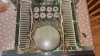
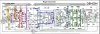
Assuming these PNP are TR536 and TR538 (I see the TR536 but the 532/534 labels in bold seem to be typos, left over from before), yes, it seems all 4 outputs on the right channel are blown.
You say F6 blew. That feeds the +72V rail, for right channel only, and that goes with TR532/TR534 being blown. Did you determine if there is a short between C and E on these two transistors, by ohming between those two pins? I would think that they probably are shorted, and verifying that might explain the difference between what you are finding on the +72V and -72V rails (see below).
Since you did not mention it, I assume you found F8 to be intact. F8 feeds the -72V rail, for right channel only, and TR536/TR538 are on that rail. TR536/TR538 are blown according to your measurements, but you ohmed between C and E pins (post #18) you did not measure a short. That TR536/TR538 have failed but not shorted C-E could explain why F8 did not blow (TBH, I am not familiar with possible multiple failure modes for these transistors, such being dead but not shorted). But you can assume the -72V rail was stressed during the failure event, and I would replace F8 even if it checks out OK.
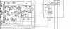
As we were discussing before, you want to go one step upstream in the circuit (this would be to TR528 and TR530**) to check for damage (also look carefully at other nearby components for any evidence of heat stress). Testing with the component tester would be best for this (although skip that if you ohm them C-E and they are shorted, as that will cause the component tester to go into self test mode again). Even if these transistors test good, you should consider replacing them anyway, and then you should be done with transistor replacements. If they are indeed damaged, replace them but also then go one further step upstream (TR524 and TR526), and repeat testing. The principle is to replace one step upstream from the last observed damage.
I have somewhere in my "notes to self" that you can get some idea if upstream damage has occurred by measuring for B-E and B-C shorts on those damaged TR532/534/536/538 transistors. If they are not shorted, it is likely there isn't damage upstream. These transistors are already removed and are easy to test for shorts, but if needed, the remaining transistors that are not yet removed can be tested for B-E and B-C shorts in circuit as well by ohming their leads.
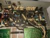
** Looking at your first photo in post #7, I see that TR528 and TR530 are heat sinked, and that TR530 has an extra nut on its tab, and two crossed black wires immediately in front of its face. I'm not positive what these are, but I think they are a sensing component (a thermal tracking diode) stuck in the hole in the tab (or near it, since the bolt is present). I first saw this in my PMA-900V, which shares a lot of circuitry with the POA-2200 (see this thread on the PMA-900V, which contains a lot of potentially useful info for you -including transistor subs- since the amp circuits are so similar, but the discussion of the tracking diode starts in post #25, and post #33 has a good photo of the diode stuck in the hole; the driver transistor in the 900V is not bolted to a heat sink, so the mounting of the tracking diode is likely to be somewhat different than what you will find in the 2200.
https://audiokarma.org/forums/index.php?threads/denon-pma-900v-troubleshooting.944587/). The equivalent sensing diode on the right channel of the POA-2200 is D528, and despite the fact that it is physically placed with TR530 (no electrical connection), it is located on the schematic in a location quite remote from TR530 (you can find it just to the left of TR522, the bias transistor). I mention this because you will likely need to pull TR530, so you have to be careful about separating that diode from the transistor (again, there is no electrical connection to TR530), and replacing it in the same position as you found it when you reinstall. There will be some heatsink compound slathered on it, and you should duplicate that when you replace. My understanding of the purpose of this sensing diode is to modify the amp's bias if TR530 starts to overheat.
Lastly, given the smashed right channel speaker terminals and the transistor damage you are now finding, it seems possible to imagine the failure event. The amp might have fallen, or had something fall onto it, while powered, and the physical damage to the right channel speaker connectors caused the right + and - wires to be shorted, leading to the electrical damage you are finding. Equally possible is the physical damage occurred while powered off, such as if the amp was dropped while carrying it, but the previous owner did not heed that damage and powered the unit on, and it was electrically damaged then.