PTL-Pioneer
Super Member
Assuming these PNP are TR536 and TR538
Yes that is a typo on my part you are correct, readings in post 19 are for TR536 and TR538
I assume you found F8 to be intact
Yes it has continuity, F6 is shot totally. Box of fuses has been ordered so will replace all the 6.3A fuses
Test Upstream in the circuit (this would be to TR528 and TR530)
Both were pulled and test ok in my component tester, can only say they are not shorted
TR528=2sa926
TR528=2sc2238
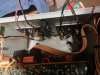
Pulling TR530, it did not have any thermal paste on it, it is like the "sensing diode" is mounted on a little circuit board, was easily removed, thankfully.
Then go one further step upstream (TR524 and TR526)
Both were pulled and test ok in my component tester, can only say they are not shorted
TR524=2sc3334
TR526=2sa1321
I also pulled the emitter resistors R634, R636 and both test and measure fine (i think), my meter seems to struggle with testing these, both read 0.1ohm (per side if that makes sense) so 0.2 ohm across each in total with the meter and tester is the same also.
I know they are supposed to be 0.36 ohm across each in total so not 100% confident in my previous statement, could it me my meter?
Yes that is a typo on my part you are correct, readings in post 19 are for TR536 and TR538
I assume you found F8 to be intact
Yes it has continuity, F6 is shot totally. Box of fuses has been ordered so will replace all the 6.3A fuses
Test Upstream in the circuit (this would be to TR528 and TR530)
Both were pulled and test ok in my component tester, can only say they are not shorted
TR528=2sa926
TR528=2sc2238
Pulling TR530, it did not have any thermal paste on it, it is like the "sensing diode" is mounted on a little circuit board, was easily removed, thankfully.
Then go one further step upstream (TR524 and TR526)
Both were pulled and test ok in my component tester, can only say they are not shorted
TR524=2sc3334
TR526=2sa1321
I also pulled the emitter resistors R634, R636 and both test and measure fine (i think), my meter seems to struggle with testing these, both read 0.1ohm (per side if that makes sense) so 0.2 ohm across each in total with the meter and tester is the same also.
I know they are supposed to be 0.36 ohm across each in total so not 100% confident in my previous statement, could it me my meter?