• The move to the new server is done. There are some software and database maintenance updates in process. This has us passing the hat around to help out. We appreciate any donations. Seriously, even a dollar helps. The payment page may be found here - https://www.audiokarma.org/support.html

Dim Bulb Tester (DBT) vs. Variac or variable autotransformer

jupitersspot

Active Member
In a separate thread I've been advised that, as part of my diagnosis of an amplifier that is blowing fuses, I should bring the machine up using either DBT or a Variac. I built a DBT this afternoon because I had those parts, but I don't have easy access to a Variac. It got me wondering about the difference between DBT and Variac, and it seems to me they're doing two very different things. But I may be wrong here, so looking for confirmation or someone to set me straight.

A Dim Bulb Tester supplies household voltage level (110v here in the US) to the test unit, but does so with the unit in series with the incandescent bulb. Let's say (for easy math sake) that I have a 110 watt bulb and my "test unit" is a complete short; we know I'm applying 110v and consuming 110 watts, so I must be current limited to 1 Amp. If instead my test unit isn't a complete short, I'll consume some watts, but I'll still be limited to a maximum current of 1 Amp. What voltage will the test unit see? It depends, and will vary by test unit and by your incandescent bulb choice. Conclusion: the DBT limits maximum current available to the test unit to (household voltage)/(wattage of incandescent bulb), but to vary the voltage I have choose my bulb wattage wisely.

I don't have a Variac, but Google informs me it's a single winding transformer where the secondary is a wiper over exposed elements of the primary. In other words you can use a Variac to vary voltage available on the secondary by sliding (or rotating, in most cases) a movable tap over the exposed contacts/windings of the primary. It's not exactly continuously variable (since you cannot step less than one winding per move), but with a fine winding it approximates infinite adjustability from 0v to household voltage. Great, but how much current will it provide? It depends entirely upon where you have the wiper positioned and the number of turns of the winding "above" and "below" the movable secondary tap; you are creating a series/parallel network with your test unit in parallel with the "lower" portion of the primary winding, and all of it in series with the "upper" portion of the primary winding. With a Variac or autotransfromer, I can set precisely the voltage I want to apply to the test unit, but I have no easy way of controlling or knowing the current drawn by the test unit.

In my view a DBT is the way to go when testing a device with a shorted circuit because it limits current available to the test unit.

When should one use a Variac or variable autotransformer?
Also, if I'm making incorrect statements, please educate me.

Moderator’s note: this awesome question and the subsequent answers have been added to our guide to DBTs, variacs and autotransformers https://audiokarma.org/forums/index...testers-variacs-and-autotransformers.1069361/
 
Last edited by a moderator:
Register to hide this ad
As you understand, you can slowly bring voltage up at small steps, current will be limited by the lack of voltage automatically.

For normal class AB output channels troubleshooting, myself I TRY use resistors as current limiters if possible for separate channels, leaving other supply voltages unaffected.
Some vintage amps have the fuses accessible when mounted inside, for those I have old blown fuses having power resistors soldered across them, enabling to limit current. I have a (metered Volts and Amps) variac but no DBT, nor do I intend to use one unless specifics ever call for it.

As with the DBT, using a variac is just better or worse, depending on what is going on and the way you deal with it.

The way you describe things, proves you are well aware of the limitations so you will do fine troubleshooting. Usually, things only go wrong by "guessing and assuming" while troubleshooting (and bad luck) .
 
variacs are usually safe with tube amps & most ss equipment but don't use it on FET type amps. generally the DBT is good tool.

I also discovered the variac with my two speed grinder sander now becomes a terrific lower speed polisher/ buffer, too.
 
You got it. A variac will limit voltage but not current. I have mine wired up with a volt and ammeter. I have powered up things with a short, and the ammeter will be over at the end of the 2 amp scale at less than 10 volts input.

Honestly I think the amp meter is a very important thing to pair with the variable voltage, otherwise you don't know what its doing until smoke comes out or a fuse blows. In case I have a stupid moment, my ammeter is fused at 2 amps, both to protect the meter and whatever is plugged into it.
 
You got it. A variac will limit voltage but not current. I have mine wired up with a volt and ammeter. I have powered up things with a short, and the ammeter will be over at the end of the 2 amp scale at less than 10 volts input.

Honestly I think the amp meter is a very important thing to pair with the variable voltage, otherwise you don't know what its doing until smoke comes out or a fuse blows. In case I have a stupid moment, my ammeter is fused at 2 amps, both to protect the meter and whatever is plugged into it.
Gadget, my variac is up to 10 amps. You wrote that you fuse limit your amp to only 2 amps. Why do the electronics makers sell up to 10 amps if only 2 is needed? I just bought 15 amp ammeter to wire in because my variac is 10 amp. Is 10 amp tremendous overkill?
 
[QUOTE="gadget73, post: 10819463, member: 20854"]In case I have a stupid moment, my ammeter is fused at 2 amps, both to protect the meter and whatever is plugged into it.[/QUOTE]

Simply; Gadget is protecting his equipment by using a fuse that sure to blow below the instrument capable rating.
No 10 amps is not overkill, the variac amp rating is simply meeting demands of user.. I saw a few at 6amp 8 and 10amp seems to be most common.
 
My own workbench has had some devices incorporated to make this type of work much easier.Inexpensive and/or easily constructed,these have become indispensible in my troubleshooting operations.

Unless you are running very high powered equipment at reduced voltages (unless they are class ''A'' types,most high powered amplifiers only draw high line current at high power output levels,and we generally aren't trying to do this at reduced line voltages) there is no need for a huge Variac.For most applications,a 3 to 5 amp type is perfectly adequate,and will tolerate short term overloads without difficulty. However,used 10 amp models are very common and are usually available for about the same money,so why not?

I use one of these panel meters with my variac,and it serves very well for monitoring purposes. As it uses a current transformer for the current/power/energy monitoring functions,it cannot be damaged by overloads.Well worth the money,but take measurements to ensure accuracy before putting it into service:

https://www.amazon.ca/gp/product/B014W3D1OC/ref=oh_aui_detailpage_o00_s01?ie=UTF8&psc=1

Here is a really nifty little device that means you will never have to replace another fuse during testing.And if you set it at an appropriate level,it can often prevent catastrophic damage during ''full power'' failures. This is undoubtably one of the best additions to any experimenters bench,and is a must for any professional tech.
Refer to page 63 for the construction article (mine has been modified to use a switch instead of a pot for current selection) :

http://www.americanradiohistory.com/Archive-Radio-Electronics/90s/1991/Radio-Electronics-1991-12.pdf
 
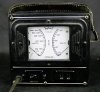
Buy yourself a Simpson 390-2 Watt Meter - when used in conjunction with a Variac, it will tell you everything you need to know about the current use of the piece of equipment your are powering up.

You simply slowly raise the voltage with the Variac - while monitoring the wattage. It the watts rise rapidly as the voltage is increased, you have excessive current draw - which means you have a problem. You will see the high current draw before you reach the normal operating voltage - Chris
 
I still have one of these (Triplett 660) on the bench,but I find the newfangled digital whatsit easier to use.Probably easier to buy too:)

wattmeter.JPG
 
Variac, aka autotransformer, is the way to safely awaken long-dormant or unknown equipment by ramping up line voltage slowly /incrementally, allowing electrolytic caps the time to regroup, reform & awaken safely. ... Dbt doesn't allow this, rather it protects the gear under test from going up in smoke if there's excessive current consumption like a dead short in it. Bulb reacts like you plugged it into line voltage (Bright light)if the piece under test has obvious issues to identify & rectify before proceeding further.
I incorporated a dbt onto my variac board with a switched outlet for the dbt. I can variac something, dbt it , or both simultaneously. To test the dbt bulb, I just shunt the test outlet to ensure I don't put a bad bulb in it. (Did that once, thought the test unit was open, it was fine but threw me off track until I figured out what the problem was).
In closing, don't use a variac to regulate speed of anything with an a-c induction motor (brushless). Their speed is regulated by frequency more than voltage. When underpowered, an induction motor pulls more current & can overheat.
 
There's also a linearity issue with variacs especially with modern electronic gear. Many (most?) DUTs/UUTs don't consume electrical power in a linear fashion due to any number of reasons, primarily having to do with transformer secondaries feeding voltage regulators designed for specific voltage input and output levels. What happens is basically NO current flows even as the variac voltage applied is gradually raised. Then, all of sudden, the device's voltage regulators switch fully on, supplying gobs of power to downstream circuitry which may or may not be in good order. If you're ONLY using a variac in one of these startup ventures, you'll see little current rise even as the voltage is ramped up from 0 to say 60 or 70 VAC. Then with the next little turn of the dial, suddenly the current spikes, the lights dim, and the smoke billows. IMO, the best way to go is using a gizmo like the catman—a combo variac AND dbt. Each certainly has its place individually, but together they just about bullet-proof the hapless hobbyist.
 
I tried posting a pic of mine, but technical difficulties arose, file too large it says, or my process is flawed, or both.:dunno:
 
Gadget, my variac is up to 10 amps. You wrote that you fuse limit your amp to only 2 amps. Why do the electronics makers sell up to 10 amps if only 2 is needed? I just bought 15 amp ammeter to wire in because my variac is 10 amp. Is 10 amp tremendous overkill?

The ammeter I used is rated to 2 amps, so I fused it for 2 amps. I have actually recently traded that for a 3 amp meter, so now its fused to 3 amps. The variac itself I think is good for 7.5 amps but it may be a 10 amp. I honestly don't remember for sure.

It all depends on what you need. Pretty much nothing I work on needs more than 3 amps, and I don't want the meter being the part that burns open if something goes badly. If you work on gear that needs more current, fuse it appropriately.
 
I use a 5 amp Variac fed by a Kill-A-Watt. Then you can measure current, Watts, VA and really monitor what's going on. With tube amps, I always start at 60 Vin to get the tubes to light up enough to conduct. SS, start at Zero volts.
 
To me, the important thing about a DBT is that it is automatic. I use a DBT with a variac, this allows me to make up for the inherent voltage drop of the DBT and still retain automatic current limiting if there is a failure after initial power up. Of course I monitor both voltage and current.
 
To me, the important thing about a DBT is that it is automatic. I use a DBT with a variac, this allows me to make up for the inherent voltage drop of the DBT and still retain automatic current limiting if there is a failure after initial power up. Of course I monitor both voltage and current.

Me Too!:thumbsup:
 
@Hyperion my use case would be a Sansui AU-X1 I got from Japan in rather unknown working conditions. It's an early version from 1978 and somebody else had already worked on it, all the problematic caps were replaced with poly caps, and other small changes I won't enumerate here. I found a few blown components on the protection circuit (a zener diode and a BD357) which I think it's consistent with the fact that the PCB holding the speaker switch suffered from multiple fractures. I have not powered it on yet, I'm at 230V, the amp works at 100V, so I can't use the DBT directly.
 
Back
Top Bottom