• The move to the new server is done. There are some software and database maintenance updates in process. This has us passing the hat around to help out. We appreciate any donations. Seriously, even a dollar helps. The payment page may be found here - https://www.audiokarma.org/support.html

Dim Bulb Tester (DBT) vs. Variac or variable autotransformer

... I TRY use resistors as current limiters if possible for separate channels, leaving other supply voltages unaffected.
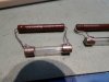
Some vintage amps have the fuses accessible when mounted inside, for those I have old blown fuses having power resistors soldered across them, enabling to limit current...
Can you please tell us what resistors you use?
 
I have not powered it on yet, I'm at 230V, the amp works at 100V, so I can't use the DBT directly.
That's a different reason for needing to use a variac - :)

But that's interesting, I also have a JDM (100V) AU-X1, which is not very happy when used with a DBT (and a step down transformer, as I am also in a 230V mains supply country ;)).

I spent over an hour chasing my tail the first time I tried the above combination, (with a 100W bulb), which gave some very strange results, until I finally realised there was no fault requiring the use of a DBT. (A change to a 150W bulb would probably have fixed that issue). I am sure you'll be happy to know I have fully reconditioned my example, it has original OP transistors, and has had the full range of stability improvement modifications, and a few others ;) - I have even replaced the 8 Main smoothing filter capacitors. Also there have been three long, detailed, and copiously illustrated threads on the AU-X1, including mine, in the Exclusively Sansui sub-forum. ;)

My thread
https://audiokarma.org/forums/index.php?threads/restoring-an-au-x1.709469/

So, if there is anything you need to know about the AU-X1, I am pretty sure I could help. :thumbsup:
 
Last edited:
When doing a quick test and most usage for me it will be the DBT when coming to solid state equipment. Tube the variac on initial powering up.
 
How should they be connected? I mean, should the DBT be the first at the household socket and then the variac and the equipment under test or variac first, then DBT and equipment?
Mine is wired for variac to feed the bulb, with the load (device under test) last. This way, a dead short can be detected early. Lots of wiring diagrams out there, I don't recall using any when assembling mine. Then again, I have electrical experience. I also use mine in other ways. Shorting plug in the DBT socket renders a straight variable power supply. I found a decorative neon bulb that I use in the bulb socket as a quick line voltage indicator. When used in this manner, it fires at 118 vac, so when winding it up, I stop as soon as it fires.
 
Can you please tell us what resistors you use?
I have used 390 ohms on several occasions. The brands I like to restore are Sansui, Luxman and Pioneer (among others) and many of the old ones have those sideways accessible fuses in the protection of output transistor circuits.
Using 10W 390 ohms usually gives a lot of protection without the resistor burning right away, but still not too much voltage drop, so it is possible to troubleshoot those amps if a power channel fails but also set amp channel bias currents.
2018_1206_205415.JPG
 
I spent over an hour chasing my tail the first time I tried the above combination, (with a 100W bulb), which gave some very strange results, until I finally realised there was no fault requiring the use of a DBT. (A change to a 150W bulb would probably have fixed that issue).

That's interesting. I will follow your path probably, so it's good to know.

My thread
https://audiokarma.org/forums/index.php?threads/restoring-an-au-x1.709469/

So, if there is anything you need to know about the AU-X1, I am pretty sure I could help. :thumbsup:

Thank you so much, I will read it as soon as I have time to invest on the AU-X1 project. I wish I could find the time to open a thread dedicated to my specimen here on AK, as I think it would be interesting to show the modifications and the issues I found. All boards were touched, even the speaker output board that was heavily modified (AKA damaged) in order to accommodate relays with larger pin spacing...
 
does anyone have a diagram or a schematic on making one with a variable transformer?
It's the same circuit as used without the Variac. You power the Variac first and then the DBT and then the unit. I believe someone did build themselves a nice one, with meters I think, and showed it on here, but I cant remember if they included the schematic.
 
I spent over an hour chasing my tail the first time I tried the above combination, (with a 100W bulb), which gave some very strange results, until I finally realised there was no fault requiring the use of a DBT. (A change to a 150W bulb would probably have fixed that issue).
I have since followed this up and used a 150W bulb - which DID solve all the issues. ;)
 
I have fisher 400 that by manual takes 200W at rated full power and 160W at 5W power as line voltage is 117V that would mean the 100W light bulb would be lit at 5W power?

So I would need a 150W modeling halogen lamp for e27 holder since normal light bulbs end to 100W to assume the bulb could then be relevant indicator of fault?

For using anything lower than 100W example 40W, 60W or 75W the lamps would be lit during normal idle condition?

Has anyone measured idle power consumption from fisher 400 at normal bias voltages?

I get the usage of variac, but could variac be used with tubes out to verify line and internal voltages at lower voltage level?

For example tune variac to give 11,7V input voltage and measure all plate and filament voltages as divided by 10? So filaments would have example 0,63V and plate 39,5V?

PS: I have a clamp meter, but no plugs to build a middle wire to measure the amp. Don't want to ruin the fisher power cord by splitting it. Living in EU. If someone has Fisher 400 and Kill-a-Watt that would be nice to post idle wattage/Amps. I might get a plug tomorrow to measure before 230V-120V dropping transformer, but it's not so accurate.

 
Last edited:
Problem with using a variac is that you might not be able to turn it down fast enough if the device it powers suddenly breaks over in some way and starts drawing a destructive amount of current. The bulb will respond right away and limit the current.
 
I have fisher 400 that by manual takes 200W at rated full power and 160W at 5W power as line voltage is 117V that would mean the 100W light bulb would be lit at 5W power?
I don't have a Fisher 400, but when you say it takes 160W at 5W power I think that means that in order to produce a 5W audio signal into a nominal 8 Ohm load the receiver (the Fisher 400) will draw 160W from the mains power. In other words, the Fisher 400, when producing a 5W audio output, would draw a current on the mains equal to 160W/117v, or 1.37A. In order to supply this amount of current, a dim-bulb-tester would have to have a bulb of at least 160W capacity. I imagine it is still possible to buy incandescent bulbs rated at 175W in most countries, but they may be hard to find. A halogen bulb would also be just fine in this situation (it's also incandescent, it just has a halogen gas around the filament, rather than a vacuum).

AK just suggested this thread - it seems very much on-topic for this discussion:
 
Well, I measured now the amps from dropping transformers primary side from 230V feed. Fluke showed 0,59 amps so that would make 0,59A*230V=135,7W idling power while input on aux and no signal. So I guess 150W lamp would be best.

If we approximite the efficiency of the dropping transformer to be around 95% that would be about 130W on the secondary side fed to fisher 400 on idle. :)
 
Last edited:
I have fisher 400 that by manual takes 200W at rated full power and 160W at 5W power as line voltage is 117V that would mean the 100W light bulb would be lit at 5W power?

So I would need a 150W modeling halogen lamp for e27 holder since normal light bulbs end to 100W to assume the bulb could then be relevant indicator of fault?

For using anything lower than 100W example 40W, 60W or 75W the lamps would be lit during normal idle condition?

Has anyone measured idle power consumption from fisher 400 at normal bias voltages?

I get the usage of variac, but could variac be used with tubes out to verify line and internal voltages at lower voltage level?

For example tune variac to give 11,7V input voltage and measure all plate and filament voltages as divided by 10? So filaments would have example 0,63V and plate 39,5V?

PS: I have a clamp meter, but no plugs to build a middle wire to measure the amp. Don't want to ruin the fisher power cord by splitting it. Living in EU. If someone has Fisher 400 and Kill-a-Watt that would be nice to post idle wattage/Amps. I might get a plug tomorrow to measure before 230V-120V dropping transformer, but it's not so accurate.
Think of the incandescent light bulb as a current limiter/fuse. note only use Incandescent lamps. If the receiver is completely shorted out the maximum current that a 100 watt bulb will allow to flow is about .85 amps at 120VAC (.42 @240). The Fisher 400 most likely has a 5 amp line fuse. Odds are that even if the primary of the transformer is shorted (not very likely) the Fishers fuse may not blow. I use a 60 Watt lamp for most of what I work on. if I have a 200 watt or higher solid state amp on my lab bench I will use a 150 watt lamp. This is due to the very high inrush current draw due to the filter caps charging. The whole idea of a dim bulb tester is that you set the variac at the lowest setting and slowly raise the voltage. If the bulb gets bright at a low voltage you have a short and you have not damaged the unit.
 
Back
Top Bottom