• Please note that Audiokarma will be offline briefly for updates early on Monday morning, September 28th.

DIY "Pro-Audio" Interconnects

Thanks for doing a comparison, Rick! I don't make enough money to buy really fancy cables to compare to, I've got to rely on my occasional borrowings or trying out other people's systems to make comparisons.

I'm glad the Canare's held up nicely! They are good solid cables, and its good to see that confirmed by another set of ears. It would be fun to try some fancier terminations, but that'll have to wait for some more cash in the bank. The F-10s would be a cheap upgrade though, they are only about 30 cents more each. ;) I think I can handle that.

peace,
sam
 
Alright, Phideaux,

It's now deigh teux of the Canare cable experiment.

I left the Canare cables between the SACD1000 and the Mod3A overnight with the player on repeat to put some time on the cables to give them a chance to strut their stuff...

Today, SWMBO's best friend is in the state, so like all good wimmen they're out shoppin'...at the factory stores in San Marcos....54 miles away....aaaaaaaaaaaahhhhhh!

What a better way to spend an non-confrontational day than making interconnects fight it out.....so, I went into my cable closet, drug out a bunch of wires, and had at it.

The contenders, in no particular order:

Original JPS Ultraconductors, 1m

Monster M850i, 1m

Wireworld Equinox 5, 1m

Stereovox HDSE, 1m

Goertz Micro Purl Silver terminated with copper Bullet Plugs, 1m

DH Labs Silver Sonic BL1 Series II terminated with Tiffany clone RCA's, .5m

Cardas 2x21.5 Twinlink terminated with Canare F-10, 1m

A DIY design based on Chris VenHaus's cable design using Cardas 21.5 ga. for the hot conductor and two runs of 20ga. magnet wire for the return/ground, 1/4" polyethylene tubing for the center tube, teflon tape, Techflex covering, copper Bullet Plugs, .5m

DIY Superconductor clone of Andrew Heliax FSJ1-50 with Axon WBT clone RCA plugs, .5m

Ixos Gamma Audition 1014, 1m

And, of course, the Canare L-4E6S with F-09 RCA's, 1m

I warmed up the system by letting it play since I got up this AM and after a heavy dose of electro shock therapy...uhhh, online paperwork for my business, a light lunch, and it was time to play!

I used the SACD of "O Brother Where Art Thou", track 4 "Down to the river to pray" just because it was nothing but voice, acapella, no instruments, so any differences are really kind of subtle...but that's what makes it fun, and challenging!

I basically found that there were three groups of interconnects, good, better, best, and any other system, or any other listener, will have different results...these are all very, very subtle differences, and if I was bothered or interrupted today I would not have been able to figure out where I felt the cables ranked.

Ok, here we go!

The good.

Why just good? Well, I sensed these cables were just a bit lacking in the areas of smoothness, definition, soundstaging, but more importantly, there's just a bit of "confusion" in the sound...now, what I mean by that is that there is just a very subtle scrim or hash on the cables...I fully admit that I have tinnitus and ANY kind of screechiness, tizziness, grunge in the top end, any upper end anomolies, just get to me and fatigue me after short periods of time...these cables all did that to a certain extent.

It's also interesting to me that all of these cables use stranded copper, non-litz conductors.

Last Place:
Monster M850i.
I could listen to this cable for less time than any other. While it's frequency response was good, it also was not very good in separating the acapella voices, everything seemed a bit too mushed together...soundstaging was OK. Shieded twisted pair stranded

Next:
Canare L-4E6S
I thought that this was better than the M850i in every way, it was less fatiguing, better imaging, deeper layering, voices were separated a bit better, soundstaging was a bit better, too. Shielded, stranded, star quad.

Next:
Ixos Gamma Audition 1014
I bought a BUNCH of these cables several years ago at MCM on close out for little or nothing, so it was natural to add them into the mix. There is a little to differentiate these from the Canare. In fact, they may tend to be more like the Monster in fatigue factor, but where they were better was in the layering of voices, the separation of the male singes from the females in the back ground, and in the fact that these guys have always had a pretty darn good soundstage, bigger than what the Canare portrays. Maybe not as quiet as the Canare. Real close to the Canare in overall quality, but the better separation and detail makes me feel like it's a bit better cable. Stranded 3 conductor type braid with a dummy conductor..i.e., two stranded copper conductors and one solid plastic rod braided under an outer jacket. Copper with polyethelyne insulation.

Better.
Why better? Well, in my case, it was purely my percieved fatigue factor, if I can listen to a cable for longer without my ears getting tired then I feel like that's a better deal. These also seemed to be a bit quieter than the previous ones.

Last Place:
Wireworld Equinox 5
My placement of this cable here surprises the heck out of me! It is a VERY smooth cable...so smooth, in fact, that for most solid state systems this could be the ticket...non-fatiguing, good soundstaging, a bit limited on layering and separation...the sound qualities displayed by this cable in comparison to the others in this group was a surprise to me as I really have used these the most between my SACD and pre over the last year! Coaxial Litz construction

Next:
Cardas Twinlink
Another smoothie! But, where the WW seems a bit too laid back, a bit too smoothed over, a bit too flattened out, the Cardas cleaned it up a bit, nice big soundstage, better layering, and better separation of Allison from the background singers. Better differentation of the male singers from the female. Shielded, twisted pair Litz

Next:
JPS Ultraconductor (original style with the blue braided cover)
Not really much to differentiate from the Cardas, but a bit quicker, a bit cleaner. Solid copper clad aluminum, twisted pair.

Next:
Goertz Micro Purl Silver
Very much like the JPS, just a tiny bit more extended, a tiny bit cleaner and a tiny bit warmer. Solid silver twisted ribbon

Next:
The DIY design based on Chris VenHaus's cable design.
This cable was very much like the last two, but opened up the soundstaging a bit, was extended without grain or glare. This is about as good as the DH Labs, but maybe a bit less extended, it has that Cardas "glow"....perhaps the silver wire would help that?

OK, now the Best
These cables all caused me to really sit back and think about what was happening here. They were clean, clear, very low grain and grunge free. The separation of the background singers' voices was much better than all but the previous DIY design. The soundstaging was huge and layered. It was also good to revisit two cables that I haven't used much lately, the JPS clone and the DH Labs, and either one of these cables was better than all but the DIY VH design.

The DH Labs Silver Sonic
When I first put this in I was shocked by the focus. Then I noticed the layering and separation, the tunefulness. I really liked this cable. Where I felt like it lost some ground to the next two was that it might have just a bit of an edge to it, but these cables had not been used in a while, and it was nowhere near what I heard with the "Good" cables. Shielded, silver clad copper, teflon insulated, twisted pair.

JPS clone made from Andrew Heliax FSJ1-50
When I put this cable in the system, I wondered why I ever took it out....oh yeah, it's STIFF! This stuff is bent into place...and then it stays there! But the sound quality from it is just sublime...that little "edge" that "might" be there from the DH Labs isn't. Smooth, clear, extended, detailed, layered, for the price of the hardline and the connectors this stuff is a steal. Another huge soundstage, wrapping around the room! My sample has also been unused for quite a while and these things do change as they get used, big time, bending them, rearranging them, letting them sit unused, and you're going to have to do some break-in to get their true sound. Solid copper corrugated shield, copper clad solid aluminum center conductor

And finally,
Stereovox HDSE
I really couldn't imagine something getting better than the JPS clones...well, this was, it was as much above the previous interconnect and the DH Labs as those two were above the Goertz. This was the most extended of all the cables here, and compared to even more expensive cables that I have heard in other systems, may not have the clean top end of $500 or more cables, but what it does it does well! The differentiation of the singers in the background, the placement of Allison Krauss, the size of the room, all were the best yet with this cable. This design is no longer current having been replaced with the Stereovox Vespa which I have not heard in my system....there is a new more expensive Stereovox cable that addresses some of the concerns that some have had with this cable, but I'll never be able to afford any!

Now, these are just my impressions of a day of listening to my system with a vocal track. Other music, other systems, other listeners will probably have different results.

So where does this leave the Canare L-4E6S with the F-09's? When you consider that you can purchase the parts from Markertek to build a 1 meter set of interconnects for less than $15, well, then, it's a slam dunk bargain! To my ears, though, I think that I would rather source some of the Heliax and go that route, IF I COULD LIVE WITH THE STIFFNESS!

The Heliax's outer conductor is a solid, corrugated copper tube. The center conductor is a solid aluminum wire clad with copper. The insulation is polyethylene foam. You make these the EXACT size you need, bend them into place, and leave them! If you don't use bearing type isolation devices like Aurios, Darumas, etc., and your gear sits pretty much motionless, and you don't swap gear often, then this is a great budget cable recipe running a little over twice the Canare price for a 1m set if you go with the 1/4 hardline and the WBT clone connectors on sale at Part Connexion right now....

If you need a bit more flexibility, then the Chris VenHaus recipe should work quite well...using the specified silver wire instead of the Cardas I used, and following his materials list more closely would undoubtably bring that interconnect up a notch, as it was it was neck and neck with the top three!

So, Phideaux, I'm glad you started this thread as it made me examine what was in my system, build a cable I hadn't built in years, and have an enjoyable day playing with the stereo,
THANKS!

And to those who don't feel like cables make a difference, well, just look how much fun I had today!

But just between you and me, well, it's gonna be a loooooong time until I bring out that SACD and play it again, man, talk about saturation!

Rick

 
Last edited:
Boy, that Heliax looks like interesting stuff.. I'll have to find a bit to play with, I've never used a SOLID shield coax before! Talk about an effective faraday cage..

Thanks for letting us know all of your experiences, Rick. And I'm glad you had a good day with man's best friend, the hi-fi. ;)

peace,
sam
 
Out of poking around DIY interconnects for no particular reason I went with Belden 1694A over Canare. It was used quite a bit also. One question belden 1694A, good or bad choice for all my audio interconnects. Flexiblity is not an issue.
 
The Belden shouldn't be too bad as long as you don't use the shield for anything but shieding....TC really has no place carrying any kind of signal, even return.....

To find out more from someone who likes Belden cable, go here:

DIY Information

.Edited January 10, 2011, Jon Risch's site on Geocities is gone...you might do a search for Jon Risch and see what turns up....the Internet keeps on evolving, doesn't it..
 
Last edited:
I just want to say that I am now the proud owner of a pair of Phidauex's home-brew IC's. My MAIN reason for acquiring these was for aesthetic purposes, rather than sonic: the mess behind my bedroom setup was sorta unsightly.

I know this could also be in the Feedback Forum, but I thought it appropriate to put it here as well.

I had been looking in a PE catalog at Dayton Audio's basic 1.5' RCA connectors when I came across this thread. I shot a PM to Phi to see if he was willing to put a set together for me - I'd rather throw an AK'er my business if it was possible.

For a pair of 1.5' cables, total cost with s/h was $15 (or as he put it, parts+beer).

Now, I'd like to say that I am not an "audiophile." As many of you here have read, I am not into perfect audio replication. I am into good, quality sound. Period. I don't have a dedicated listening space, I don't have a record washing machine, and I don't have AR-9's.

I have always used standard, generic stock cables/IC's and wanted to upgrade based purely on my need to clean up the tangled mess that collects behind my equipment. My bedroom system is very simple and modest: KA-7100 (refurbed by EW), a Yamaha T-4017 tuner and a Sony CDP-311, all played through a pair of Polk RTi-28's.

My test music was Lou Reed's remastered "Berlin" CD. Specifically the 3rd track, Men of Good Fortune.

When I A/B'd the Phi-IC's with the generic IC's there was an OBVIOUS difference to me, and I wasn't even sure what I was supposed to be listening for! There was a subtle clarity that was now present with my new Phi-IC's.

I also appreciate how the cables are clearly labled with "source" sides. A+ job, Sam! Thank you very much.
 
Changed the images to attached, instead of linked from my webspace. It means using more AK bandwidth, but it also means more consistency, since a few people have mentioned not being able to see the images occasionally!

-Sam
 
Following phidauex's directions, I have built a couple of pairs of cables and I am a believer! I do not know if they sound better, but damn, they look and feel great! The whole thing just feels like a quality cable. I even went the extra yard and got colors! Yes! Red, black, white, yellow, orange, blue, green, purple. This cable, from markertek, is cheap so I got 30' of each. I figure the total cost for a potload of cable and connectors is still less than the cost of a pair of "designer cables". And they feel so good.

Thanks phidauex!
 
Glad you like them, spiff! The Canare gear is meant to last, it feels really nice to use, has a good solid grip, and will last a looong time. Enjoy!

peace,
sam
 
Xlr

Phideaux, do you have a similar set of instructions for XLR analog cables? I am going to make a few for my McIntosh equipment. My plan was to order some from Markertek and try to copy them. It would be great if you already know how to do this.

Thanks,

Bill
 
Hi Bill,

XLRs are easy with Star Quad cable. I like using Neutrik XLR connectors, something like their XX or XX-HE series, they are all good though, I just like how their connectors work, they feel good to use, and are very durable. Canare XLRs are good too. Switchcraft connectors are a good deal, but I don't think they are as durable.

Basically, carefully disassemble the XLR body, and slide the chassis over the wire. Strip the wire as normal, pulling the shield back a bit.

Strip the two white wires, and connect them together. Then strip the two blue wires, and connect them together. Now, the whites will be the positive signal, so connect them to pin 2. The blues are the negative signal, so connect them to pin 3. The shield connects to pin 1. The chassis remains floating (not connected to anything). Unlike the unbalanced interconnects, you DO want the shield connected at both ends. In this case, the shield is ONLY a shield, it carries no signal, so a ground loop isn't created by connecting it at both ends. Slide the chassis back up over the connector body, and tighten it down. I don't use any heat shrink, or any strain relief other than what the connector chassis provides. You can mark the sides with heat shrink to designate left or right, if you want, but there is no need to add a 'source' marker, since the wires are symmetrical.

Which pin is which? When looking at a female XLR face on, with the locking tab up, Pin 1 is top right, pin 2 is top left, and pin 3 is the bottom. Usually the connectors have little numbers by the pins to help you remember. The XLR mnemonic is "Shield, Live, Return". :)

Occasionally manufacturers swap the + and - pins, but if they are following the standards for balanced connections, then the above should be right.

peace,
sam

EDIT: On reflection (see below), for balanced lines, connect the shield at ONE SIDE ONLY (typically the source side). If the balanced line will be used for microphones, musical instruments, or other non-mains-powered devices, then connect the shield at BOTH sides.
 
Last edited:
Xlr

I looked in the Markertek catalog: They have an XX and an HD series. The HD is water resistant, heavy duty,etc. Is that what you mean instead of XX-HE?

Thanks,

Bill
 
phidauex said:
Unlike the unbalanced interconnects, you DO want the shield connected at both ends.

phidauex, I respectfully disagree with this comment. In fact, this made me read your first post in this thread and I can't really agree with a comment there as well. In an unbalanced system, it is not possible to make a connection that won't provide a path that would support a ground loop. Connecting the shield on only one end of the unbalanced cable doesn't break the ground path when you've got two blue wires connecting the ground of the two pieces of gear together. Although, NOT connecting the shield at one end (as suggested) doesn't have any adverse effects.

Conversely, in balanced systems, reference to ground is not really necessary and NOT connecting the shield at one end (usually the receiving end) will break any chance of a ground loop.

At least, that's my take on this topic.
 
House de Kris said:
phidauex, I respectfully disagree with this comment. In fact, this made me read your first post in this thread and I can't really agree with a comment there as well. In an unbalanced system, it is not possible to make a connection that won't provide a path that would support a ground loop. Connecting the shield on only one end of the unbalanced cable doesn't break the ground path when you've got two blue wires connecting the ground of the two pieces of gear together. Although, NOT connecting the shield at one end (as suggested) doesn't have any adverse effects.

Conversely, in balanced systems, reference to ground is not really necessary and NOT connecting the shield at one end (usually the receiving end) will break any chance of a ground loop.

At least, that's my take on this topic.

Hmm.. Well, I'm not claiming to be a 100% authority on the topic, I'm just passing along what I felt was the 'best practice' based on my knowledge of theory and my experiences.

First, unbalanced cable:

Many unbalanced cables have only two conducting paths, like coax, with a shield path and a center conductor path. In this case, you have no choice but to connect the shield to the connector ground, and the center conductor to the center pin.

However, when using star quad, or other two conductor + shield cables, we have THREE possible conducting paths. One should be the center pin of the connector, of course, but then we have to decide what to do with the others. I like to use the other inner conductor as the signal ground. But then what to do with the shield? If you leave it disconnected, it won't do much good at all. If you connect it at one side, you ground the shield, allowing it to reject noise. If you connect it at BOTH sides, you ground the shield allowing it to reject noise AND you increase the capacitance of the cable, which can leave it more open to induced currents, without improving the overall shield characteristics. So while its fine to connect the shield at both ends, it makes sense to leave it off of one end.

Canare's datasheets said:
Two conductor twisted pair cable such as L-2B2AT (or 4-cond L-4E6S Star Quad) are intended for Balanced circuits, but may also be used for Unbalanced assemblies. One of several wiring tricks, is to solder the blue conductor to the connector's center pin and the white conductor to the shield ground contact. An installer may then choose to "float the cable shield" by not soldering the overall braid (or drain wire) at one or both ends of the cable. This technique may result in better "unbalanced" circuit noise rejection.

In other words, with the shield connected at both ends, noise induced in the shield is added in series to the signal ground path, but with the shield connected at one end only, noise induced in the shield does not get added to the signal.

Now, as to Balanced assemblies, its a little simpler. We've got three pins, and three conductors, thats pretty easy. The two inner conductors are the signal and its inverse, and the outer conductor is the shield, but do we connect it at one, or both, or no ends?

Upon reflection, I'm going to agree with you, Kris. For microphones and other non-mains powered instruments you want the shield connected at BOTH sides for best noise rejection, and to provide a return path for phantom power current.

But for connected between two mains powered devices, then leave the shield connected to one end only, to prevent ground loops in gear that may not be properly mains grounded.

I was thinking about microphones (which is what I built the majority of my balanced interconnects for), and hadn't considered that most people here wouldn't be using mics, but would be connecting balanced audio gear. It won't hurt to connect the shield to both sides, UNLESS your gear isn't properly grounded, in which case it could create a ground loop problem.

So anyway, with unbalanced, I think I'm still right, and for balanced, Kris's suggestion of only connecting on one side is a good one, unless you are making the cable for microphones or musical instruments.

peace,
sam
 
Last edited:
willjrichard said:
I looked in the Markertek catalog: They have an XX and an HD series. The HD is water resistant, heavy duty,etc. Is that what you mean instead of XX-HE?

Thanks,

Bill

Yes, the connections are solder-on connections. Neutrik has a lot of series of connectors, not all of which are available at Markertek. The XX is their basic standard, and is a good connector. If you'll be using your high end CD player out in the rain, then I'd recommend the HD. ;)

peace,
sam
 
phidauex said:
However, when using star quad, or other two conductor + shield cables, we have THREE possible conducting paths. One should be the center pin of the connector, of course, but then we have to decide what to do with the others. I like to use the other inner conductor as the signal ground. But then what to do with the shield? If you leave it disconnected, it won't do much good at all. If you connect it at one side, you ground the shield, allowing it to reject noise. If you connect it at BOTH sides, you ground the shield allowing it to reject noise AND you increase the capacitance of the cable, which can leave it more open to induced currents, without improving the overall shield characteristics. So while its fine to connect the shield at both ends, it makes sense to leave it off of one end.
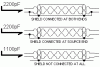
Thanks for the clarification. When I read it, it seemed to be a bit backward, so I decided to do a little reality check and just do some real life measurements. I took a length of balanced microphone cable and measured the capacitance in three different configurations. First, with the shield connected at both ends, then at one end, then at neither end. If your desire is to lower capacitance, then connect the shield at neither end. There is absolutely no difference if you connect one end of the shield or both ends. With no shield connection at all, I measured 1100pF. With one or two shield connections, I measured 2200pF. I've attached a drawing of the three setups for clarity.
 

Attachments

  • coax.gif
    coax.gif
    4.3 KB · Views: 234
Last edited:
House de Kris said:
Thanks for the clarification. When I read it, it seemed to be a bit backward, so I decided to do a little reality check and just do some real life measurements. I took a length of balanced microphone cable and measured the capacitance in three different configurations. First, with the shield connected at both ends, then at one end, then at neither end. If your desire is to lower capacitance, then connect the shield at neither end. There is absolutely no difference if you connect one end of the shield or both ends. With no shield connection at all, I measured 11pF. With one or two shield connections, I measured 22pF. I've attached a drawing of the three setups for clarity.

Curse you and your 'empirical' evidence! I wish I had as sensitive of measurement instruments at my disposal. ;) I'll have to use your abilities more often!

So, I was wrong the capacitance doesn't go up, but I'm still thinking that connecting at both ends A) Does nothing to improve the noise rejection B) could hurt noise rejection by putting the noise source in series with the signal ground, instead of in parallel with it. I wonder if we could simulate it in a circuit sim...

peace,
sam
 
Well, this may be getting a bit theoretical for this thread, but let me run this past you, Kris.

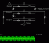
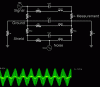
I'm trying to model an interconnect as a discrete circuit, which is a task fraught with danger. But I'm trying anyway...

Each of the three lines is modeled as a series inductor and resistor, with a parallel capacitor. The ground and signal lines are separated by 10k resistors on each side, and the shield is connected to the ground by a low value resistor on one side, or both sides, depending on the sim. The ground reference is connected to ground through a low value resistor on both sides, and there is a 60hz 'noise' source attached to the shield. The measurement point is across the 10k resistor between signal and ground at the load end.

Image one is shield connected at one side, image two is shield connected at both sides. Ignore the component values, this is just meant as a comparative exercise, so they don't need to be right, just correct relative to each other (ie, resistor to ground much lower than between signal and ground).

The first image, with shield connected only at one end, shows far less penetration of the noise source into the final output signal, suggesting that floating one end keeps the noise source from being a part of the ground reference line.

I'm not trying to 'prove' anything with this, I'm just experimenting. I welcome your thoughts.

peace,
sam
 

Attachments

  • wiremodel-noisedrain.gif
    wiremodel-noisedrain.gif
    11.2 KB · Views: 101
  • wiremodel-nonoisedrain.gif
    wiremodel-nonoisedrain.gif
    11.2 KB · Views: 80
YIKES, really opening up the proverbial can-o-worms, eh? Unlike digital circuit simulators, simulating analog circuits leans a bit towards the 'art' end as opposed to the 'science' end. In other words, how well you model the circuit and its environment plays into how well the simulation mimics real life.

The way you've modeled each conductor is to have an L and R in series with a C in parallel to that. I believe the L and R are correct, but the C would be a parallel network between conductors. Next big question is, how should the noise source be modeled? You've got it as a voltage source with respect to the system ground. Perhaps it should be a differential voltage source applied across the length of the cable, or a current source in series with it. Really, I don't know, I'm just tossing up questions here.

I did attempt to do a simulation of a cable with similar components you've got here, and found that I wasn't comfortable enough with the cable model and how I was injecting a noise that I wasn't inclined to continue with it too far. But, I say keep plugging away, you may be onto something here.
 
Back
Top Bottom