• The move to the new server is done. There are some software and database maintenance updates in process. This has us passing the hat around to help out. We appreciate any donations. Seriously, even a dollar helps. The payment page may be found here - https://www.audiokarma.org/support.html

Dynaco 6v6 Ultra Linear Tube Amplifier PCB Questions

KCharlemagne

New Member
Hello,

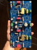
Another post seeking help wiring a nondescript Dynaco tube board from Ebay. This one is a Dynaco 6v6 ultra linear circuit. I have the power supply issue under control, but I'm looking for advice on how to properly wire the output transformers to the board. I've read that the OPT for ultra linear needs to have 5 primary taps? Is this correct (seems consistent with board)? If so, a brief conceptual explanation of why this is the case would be much appreciated. I assume the "SG" 1-4 and "P" 1-4 solder points stand for "screen grid," and "plate." Do "L-FB" and "R-FB" stand for left and right feedback?

Anyone have any recs on OPTs for this circuit other than Hammond 1608 series?

Thanks!
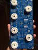
28343261_2057874254489149_596882378_o.jpg 28309545_2057874257822482_283911809_o.jpg
 
Register to hide this ad
I would make the same assumptions you did regarding the labels. Only question about the feedback is whether you're meant to tie it straight to the secondary, or if you need a resistor in there to set feedback level. If that FB tie point has a resistor in the 1K-10K ohm range between it and the cathode of the driver tube, you probably do not need an external resistor.

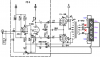
UL transformers do indeed have 5 leads on the primary. Secondary can be any number of leads, doesn't really matter. Maybe a schematic drawing of one will make it clear why that is.

st-70 modified schematic.png

Thats basically an ST-70 with some modification that doesn't matter for our purposes here.

The five leads are, from top to bottom, plate, screen, B+ input / center tap, screen, plate. The screen leads are connected to the winding somewhere between the point where the voltage feeds in and the plate. There are different tap points for this too, but 40% and 23% seem to be the common ones. Depends on the tube which works better.

The idea with a UL circuit is that the screen gets some amount of feedback from the plate. A pentode output stage just has DC voltage on the screen. A triode stage will have the screen tied to the plate. UL is in between those two. Transformers for triode and pentode operation have only 3 primary leads, the two plate connections and the B+ feed. The goal is triode-like distortion and output impedance with power and gain like a pentode. You'll get arguments all day long about how well it worked, whether it was a good idea in the first place, and what the best output stage design is but thats what the designers and proponents of the circuit had to say about it.

also worth mentioning but you can make this work in triode or pentode mode depending how you wire it. A 100 ohm resistor between the plate and screen connection makes it triode, a connection to a straight DC source makes it pentode, so it is possible to use this board with a non-UL transformer if you need or want to.
 
half suspecting it was intended for the components to go on the other side. Either that or someone goofed. Also possible they couldn't have done 2 sets of holes for some reason.
 
half suspecting it was intended for the components to go on the other side. Either that or someone goofed. Also possible they couldn't have done 2 sets of holes for some reason.

In the pic of the blank PCB it shows the mounting screws on the face which puts threads on the back.

Perhaps the guy doing the layout had a brain flat.
 
Back
Top Bottom