• The move to the new server is done. There are some software and database maintenance updates in process. This has us passing the hat around to help out. We appreciate any donations. Seriously, even a dollar helps. The payment page may be found here - https://www.audiokarma.org/support.html

Dynaco MKii/iii triode kit project

I was only looking to reduce the power transformer internal heating.
The actual heat from the rectifier itself doesn’t matter but the losses in the transformer from the 5 volt winding were what I was after. They can’t be a full 15 watts.
I probably should measure the power going into the amp at idle with each setup.
I’ll see if I have a suitable resistor to add to the diodes. I didn’t think that the inrush heating would equal the losses needed to power a resistor…
 
Added a 47 ohm resistor.
I’ll give it a test run this evening.
I’m comparing the temp of the two power transformers, as I know that the one with the SDS board runs hotter than the other one, typically just under 10 degrees F.
Nothing I’ve done has really impacted that.

I’ve decided that the temps are OK, so really this is just typical messing around.

IMG_9764.jpeg
 
the losses in the transformer from the 5 volt winding were what I was after. They can’t be a full 15 watts.

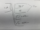
if you know the DC resistance, 9 (3 squared) times the DC resistance of the 5v winding will give you the heat from that winding.

Primary side is a little more complex but its a 24:1 winding so 3 amps / 24 = 0.125, which is the primary current to supply the secondary. Power formula for amps and ohms is amps squared times ohms or 0.0156 times whatever the primary resistance is.

add the two together to get the total heat.

its probably not going to be all that much.
 
Not easy enough to measure.
The resistance of the 5V winding is too low for me to measure. It seems to be less than 0.1ohms.
 
Added a 47 ohm resistor.
I’ll give it a test run this evening.
I’m comparing the temp of the two power transformers, as I know that the one with the SDS board runs hotter than the other one, typically just under 10 degrees F.
Nothing I’ve done has really impacted that.

I’ve decided that the temps are OK, so really this is just typical messing around.

View attachment 3746970
FWIW, if I were you, first of all. if those SS rectifiers are 1N4007s I would double them in series to get more PIV headroom, as I painfully first learned in 1977 with my first SS rectifier conversion of a ST70, and secondly, if you tend to crank your stereo using these Mk IIIs it is recommended to replace that 5 watt 47 ohm sand resistor with a 10 watt version for long term thermal headroom.

I personally never used a tube rectifier emulating for dropping the B+, but instead used a CL80 thermistor inserted in the power transformers primary for turn on inrush soft starting and to provide a few volt drop to bring the higher modern mains (120 +) voltage closer to the lower mains (110~117 at the time of these amps design era.

Just my suggestive thoughts owning and using 2 pairs of Mk IIIs SS rectified since the early nineties, plus my B-I-Ls pair, thus also converted, with only the over time wearing out of the modern KT88 outputs and 6AN8 driver tube, until I changed out mine to the PS cap board & modern dual triode boards ~15 yrs. back, with no other issues for any of Mk IIIs.
DSCN0111.JPG
 
The rectifier tube itself could be adding heat to the transformer. There is one power tube and the rectifier close to it. After replacing the 5AR4 with a WZ34 coppertop SS rectifier in my ST-70, the output transformer the 5AR4 was sitting in front of runs cooler.
Added a 47 ohm resistor.
I’ll give it a test run this evening.
I’m comparing the temp of the two power transformers, as I know that the one with the SDS board runs hotter than the other one, typically just under 10 degrees F.
Nothing I’ve done has really impacted that.

I’ve decided that the temps are OK, so really this is just typical messing around.

View attachment 3746970
I need to make another one of those. I made one sometime back using a piece of copper tubing and a copper cap I found at Lowes. They and Home Depot have copper pipe fittings in the numbing area. The copper tubing fit nicely inside the socket. I used epoxy to attach the tubing and cap.
 
Since I have the ‘yellow sheet’ mod below deck, I do have two 1N4007’s in series. I’m also using a bucking transformer to drop ~6.3vac from the line. It’s needed to keep the heater voltages down.
I’m not really sure if SS conversion is temporary or not yet. My main goal with this experiment was to see if doing so dropped the temperature of the power transformer, and so far it has not had a noticeable effect.
Likewise with only one of two amps converted, I’m not sure if I can notice any difference in the bass vs the 5AR4.
Dual bias is still in the cards though.
I do have some CL80’s…
 
The 5AR4 shouldn't have any voltage sag problems at higher volumes effecting bass. But, it does put stress on the 5AR4 that doesn't happen with a SS rectifier.
 
just as a point of reference, I happened to have my IR gun out so I shot the transformer in my Magnavox 9300. This runs a 5AR4 instead of the 5U4, a 47uF first cap. Total idle draw on the power supply is probably very close to 100mA. I've had it playing for several hours and the transformer is sitting at 139F at the lamination stack and its 83F in here according to the temperature gun. Weather app says 85, so thats probably about right.

this is running the extra 6v winding in bucking config too. It runs hotter without that. In stock form this would have had more current load on the B+ and it would be using the other heater winding to power the tuner, so fair guess it ran even warmer 60 years ago.
 
Using the ohms @nerdorama measured only gives 0.4 watts of losses in the power transformer by getting rid of the heater current. I don’t know why I thought it would be more.
I went back to the 5AR4 for now.
 
This is the hottest one of mine.
It’s been running about 4 hours.
I’m running on a 6.3 volt filament bucking transformer.
My other one is running 137F with the same gun. It’s always been this way, which made me wonder if it was something about the build that made it run hotter.

If I want it cooler I’ll need a fan…
 

Attachments

  • IMG_9802.jpeg
    IMG_9802.jpeg
    252.6 KB · Views: 16
This is the hottest one of mine.
It’s been running about 4 hours.
I’m running on a 6.3 volt filament bucking transformer.
My other one is running 137F with the same gun. It’s always been this way, which made me wonder if it was something about the build that made it run hotter.

If I want it cooler I’ll need a fan…
I know it's probably buried in the thread somewhere, but what value are you setting bias at? I can tell you that for a long time I was running 55 mA (don't know or remember why) and it did run hotter. I set for 50 mA max now, sometimes it dips lower depending on mains level and it runs pretty consistantly where i measured.

I do have separate bias pots with 10 Ohm resistors at the cathodes to read across. If you have some different set up, you'd have to account for that when comparing.
 
I’ve been running 6550’s at about 1.50 volts across the 11.2 ohm resistor. So a lot more current.
I’ll try running them cooler. Seems like I used to do that…
50 mA is only 1.12 v right? Don’t know if I ever ran that low.
 
Yes, I think that's right. 1.12 / 11.2 would be 100 mA total between 2 tubes.

I think another consideration is the speakers you're driving. I'm using 99 dB Klipsch Forte. My 3.5W SET will drive me out of the room pretty easy. These 60W are barely running to get 80dB from my listening spot.
 
Back
Top Bottom