• The move to the new server is done. There are some software and database maintenance updates in process. This has us passing the hat around to help out. We appreciate any donations. Seriously, even a dollar helps. The payment page may be found here - https://www.audiokarma.org/support.html

Dynaco MkIII restoration - join the ride

sabrefencer

AK Subscriber
Subscriber
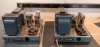
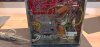
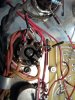
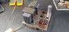
I know I'm not the first, but I have started a restoration/"upgrade" of a pair of Dynakit MK IIIs and want my AK friends to join in on the fun. These were recently acquired from fellow NC AKer Nolasally, are completely original and they checked out OK on the bench, so there should be no big surprises. Based on my read of the date codes on the bias pots and transformers, I think one is a '59 and the other a '64. I realize there are lots of options on how to restore/restomod these, but I have done my research and have decided on a plan – unless someone credible tells me I’m nuts on a particular item .

Summary plan: Keep original audio circuit with 6AN8A, KT88s, and GZ-34 rectifier. Update bias to SS rectification (remove selenium), upgrade power supply cap voltage rating to 630v, replace all resistors with metal film, replace power switch and input jack, and re-wire with 600V Teflon insulated silver plated wire (20AWG).

Details:
Strip down to bare chassis and clean/remove light surface rust, finish with a very light coating of high-quality carnauba wax. Clean and lightly wax transformers. Clean and re-tension octal sockets. Replace power cord with polarized 2 prong 18awg, install new power switch, add CL-80 thermistor in series with fuse and power switch in the hot leg, connect neutral leg directly to power transformer. Replace all fasteners with stainless steel, slotted pan-head in original sizes.

1) Rebuild power supply using two 68uF 450v, 105C caps in series, with one 0.1uf 630v film cap, and two 100k Ω 1/2w bleeder resistors per “section”. Each section will be rated at 34uf 630v. These components will be mounted on a perf board under the chassis.

2) Replace driver boards with new boards using stock circuit, stuff with all new components, including Solen fast caps.

3) Install matched quad of Genelex Gold Lion KT88 output tubes (new Russian production).

Updates from original circuit:
4) Replace the selenium rectifier with a 1N4007 diode and 4.7k Ω 1W resistor, replace 18k Ω 1/2W with 18kΩ 1W resistor, and replace bias caps with 100uF 100v electrolytic axial. Install new 0.02 ceramic Z5U @500V ceramic cap.

The next two mods seem like good practice, but looking for specific feedback to confirm:
5) Install diode modification on the GZ-34 socket per the “yellow sheet” (Dynaco Tube Audio Forum 11/7/2011), but use UF4007 fast recovery diodes instead of 1N4007. I have been debating on whether or not to ditch the GZ-34 and go with SS rectification, but for now I have decided to keep the tube to retain the original circuit. I have two good rectifiers, and can always switch to SS later.
6) Install output screen stability resistors (100Ω 1/4w), per Dave Gillespie recommendation (1/9/2020 AK post).

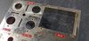
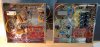
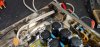
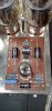
Did I forget anything, or are any of the above ideas ill advised? I look forward to constructive comments/questions. Posting "before" photos now, and will update with in-progress photos soon.

Gary.
0213211608_HDR.jpg 0213211609_HDR.jpg 0213211549a_HDR.jpg 0213211604_HDR.jpg
 
Register to hide this ad
I think you're doing more than you need to, but it's your project. Personally I like to keep everything that's still good and only fix what's broken.

Whatever way you go the end result will be good sound. Enjoy the resto.
 
I'd sub a 5AR4 and use the *enhanced* yellow sheet mod to max reserve power.
And I'd adjust the screen voltage on the 6AN8 to get the 25/50/25% triode section splitter distribution ratio.
 
Pio,
I'm not sure I understand your post - what you refer to is new territory for me, but I'm eager to learn.
When you say "sub a 5AR4" are you referring to using a new production (e.g. Russian) tube, vs. a vintage GZ34/5AR4 tube (which is what I have)? I have not found any reference to the "enhanced" yellow sheet. Regarding adjusting screen voltage on 6AN8, I have found references to using pots to adjust resistance. Perhaps these are mods that I can consider for future work, once I get these amps sorted out and running (close to stock).
 
Pio,
I'm not sure I understand your post - what you refer to is new territory for me, but I'm eager to learn.
When you say "sub a 5AR4" are you referring to using a new production (e.g. Russian) tube, vs. a vintage GZ34/5AR4 tube (which is what I have)? I have not found any reference to the "enhanced" yellow sheet. Regarding adjusting screen voltage on 6AN8, I have found references to using pots to adjust resistance. Perhaps these are mods that I can consider for future work, once I get these amps sorted out and running (close to stock).
Yes, any decent modern 5AR4/GZ34, general availability, greater current capacity, lower resistance, lower heater current than 5U4. The diodes assure that the reverse voltage isn't a consideration as a failure mode and do the rectification for the tube.
The "enhanced" (my term) yellow sheet mod uses two diodes in series on each leg of the red HV windings and ties the opposite ends of the diode strings together, effectively paralleling the halves of the rectifier tube and doubling its current carrying capacity as a time delay resistive series element in the B+ supply.
20210303_090156.jpg

Dave Gilllespie determined that the ideal operating cdx for a "concertina" cathodyne phase splitter puts the voltage distribution ratio @ 25% across the cathode resistor, 50% across the cathode/anode of the triode, and 25% across the anode resistor. Adjusting the screen voltage of the direct coupled pentode section is the best way to assure this. An approximate correction can be made by reducing the 1.5 meg screen resistor by ca half, 750-820-ish k, or precisely for the individual driver tube with a 1 meg Cermet Trimpot wired as a rheostat.
An additional benefit is the reduction of the voltage differential between heater and cathode of the triode section.
 
Last edited:
Sabrefencer, I am planning a similar restoration of a single Mark III. Since you are pulling out all of the stops, you might also be interested in another clever idea, one which you didn't mention. It is in page 5 of a response by Retrovert to a Tube Audio thread entitled Dynaco PAM-1 Upgrade. He proposed using a 555 IC in a circuit to delay the power-on voltage surge until the tubes have warmed up a and stabilized.
 
Once upon a time it was a Dynaco MkIII ...
And it can stay basically that, but better. Changing the topology makes it something else entirely. Tweaking a circuit point and tightening up the ps doesn't change that much.
It's sort of like putting dippers on model T Ford con rod caps to improve crank lubing, rather than making a hot rod with just part of the body.
 
I am more in line with Pio's comment above. I do not want to significantly change the topology, for example by putting in a driver board that runs a 12AU7, that would make it not a MkIII. I am looking to keep the MkIII circuit, with the under capacity PS taken care of, the selenium rectifier gone, and any other tube related issues addressed, that is it, other than replacing 60 year old parts with new equivalents. For example the brittle driver boards, one of which cracked upon careful removal. I want these to sound like the MkIII Hafler designed, not a modern interpretation. To continue Pio's car analogy, if this were a '63 split window Corvette, I would not hesitate to put in all new suspension bushings, new break lines, and new tires, but I would not replace the 327 with a motor from a Z06. I guess this project sounds complicated because I am taking the amps completely apart, but these are relatively simple units, and putting them back together is just like building the kit all over again. As for ICs, they will not have a place in this project, I will let the CL-80 handle the surge. Thanks for the input, keep it coming.
 
Yes, any decent modern 5AR4/GZ34, general availability, greater current capacity, lower resistance, lower heater current than 5U4. The diodes assure that the reverse voltage isn't a consideration as a failure mode and do the rectification for the tube.
The "enhanced" (my term) yellow sheet mod uses two diodes in series on each leg of the red HV windings and ties the opposite ends of the diode strings together, effectively paralleling the halves of the rectifier tube and doubling its current carrying capacity as a time delay resistive series element in the B+ supply.
View attachment 2183132

Dave Gilllespie determined that the ideal operating cdx for a "concertina" cathodyne phase splitter puts the voltage distribution ratio @ 25% across the cathode resistor, 50% across the cathode/anode of the triode, and 25% across the anode resistor. Adjusting the screen voltage of the direct coupled pentode section is the best way to assure this. An approximate correction can be made by reducing the 1.5 meg screen resistor by ca half, 750-820-ish k, or precisely for the individual driver tube with a 1 meg Cermet Trimpot wired as a rheostat.
An additional benefit is the reduction of the voltage differential between heater and cathode of the triode section.

Pio,
I'm going to need some time to absorb these recommendations, but they have my curiosity up, and don't seem too difficult. I will likely be back with some questions. Thanks.
 
I used a populated replacement board on my Stereo 70, and replaced the two 1.5meg screen resistors with 1.0 meg ten turn Cermet pots wired as rheostats. The Mk-3 is similar as one half, set pot range half way when installing them. The final setting is made with tubes in and warmed up, it's measured across the *in* end of the two caps from the triode splitter to the output tubes. Adjust for one half the voltage to chassis as measured from the top of the triode splitter anode resistor. The other half is split between the cathode and anode resistors, each at ca one quarter the total. Setting may differ somewhat for individual driver tubes, but otherwise should stay stable for much of the service life of the tube
 
Pio,
Regarding the 5AR4 diode mod. As far as understanding it conceptually, not sure I am there yet. It looks simple enough to implement, but I don't like to do stuff I don't understand at least a little bit. I think you mention this, but is that red wire connecting the diode strings from pin 4 to pin 6? Also, can/should I substitute UF4007s for the 1N4007s? I have both.

Regarding replacing the screen resistors for the 6AN8 with trim pots I get that. Do you have a specific PN that you used, I need to mount these in 15mm lead spacing on my board. To connect as rheostat, do you connect the center (wiper) terminal and one of the other legs? Do you cut off the third (unused) leg?
Thanks for your help.
Gary
 
Pio,
Regarding the 5AR4 diode mod. As far as understanding it conceptually, not sure I am there yet. It looks simple enough to implement, but I don't like to do stuff I don't understand at least a little bit. I think you mention this, but is that red wire connecting the diode strings from pin 4 to pin 6? Also, can/should I substitute UF4007s for the 1N4007s? I have both.

Regarding replacing the screen resistors for the 6AN8 with trim pots I get that. Do you have a specific PN that you used, I need to mount these in 15mm lead spacing on my board. To connect as rheostat, do you connect the center (wiper) terminal and one of the other legs? Do you cut off the third (unused) leg?
Thanks for your help.
Gary
The UF4007 is fine for this application. The red jumper puts the positive source of each diode string on each transformer secondary leg together as a complete diode full wave bridge, and puts both rectifier sections in parallel, doubling the current capacity of the tube. It's like having two 5AR4s in parallel without the diodes, and the diodes take the reverse voltage, the tube never "sees" it, so cannot break down from it. You get the time delayed ramp-up of the tube without the tube rectifier problems of the newer versions, the older ones should last a long time, plus the current limiting of the single tube is greatly reduced for greater peak and sustained power.
 
Last edited:
Re the Cermet 1K pot, connect one leg to wiper to configure as rheostat. I used what I could order from a reliable supplier and adapted to fit. One of the square ten turn 1 meg Cermets that mounts on one side should be adaptable, or you can try a fixed metal film ca 780k-820k to see how the distribution ratio looks. It doesn't have to be exact.
 
Very helpful. Thanks. May go with this diode mode on the 5AR4 in my Fisher X-101-ST also, that restoration is on deck.

I think I found a trimmer that will work. Going to add it to my next parts order. If the amp was up and running, I would dial it in with a decade resistance box, and then put in the nearest fixed resistor, but if I will have the trimmer before the amp gets finished, and if I can get it to fit on the board and look decent, I will go that route.

Thanks.
 
The rectifier mod with an ss diode in series with each GZ34 anode just provides protection to the GZ34 diodes if ever they go gassy and arc. Each ss diode operates benignly up until the GZ34 goes leaky - there is no advantage in using a UF4007 compared to a 1N4007 (as the ss diode does not modify the turn-off transition), and possibly a disadvantage in that the UF4007 has higher leakage and has a lower PIV.

The rectifier mod that Pio suggests is a significant change, as the two GZ34 diodes are paralleled and so the B+ level at idle and during operation will change.(increase). The default B+ is already 480Vdc, so you would need to be confident that you aren't about to stress parts in the amp. There may also be a subtle change in commutation noise - that is trickier to define.

Make sure you carefully clean between the octal pins on the GZ34 socket, as pins 5 and 7 are now being used, so there is now a high PIV between adjacent pins if connecting diodes as per that photo.
 
The rectifier mod with an ss diode in series with each GZ34 anode just provides protection to the GZ34 diodes if ever they go gassy and arc. Each ss diode operates benignly up until the GZ34 goes leaky - there is no advantage in using a UF4007 compared to a 1N4007 (as the ss diode does not modify the turn-off transition), and possibly a disadvantage in that the UF4007 has higher leakage and has a lower PIV.

The rectifier mod that Pio suggests is a significant change, as the two GZ34 diodes are paralleled and so the B+ level at idle and during operation will change.(increase). The default B+ is already 480Vdc, so you would need to be confident that you aren't about to stress parts in the amp. There may also be a subtle change in commutation noise - that is trickier to define.

Make sure you carefully clean between the octal pins on the GZ34 socket, as pins 5 and 7 are now being used, so there is now a high PIV between adjacent pins if connecting diodes as per that photo.
The mod isn't mine, but brilliant in its simplicity as an improvement on a limited compromise to use a single rectifier tube.
 
It's been a few weeks, and I have not forgotten my promise to post photos of the restoration. The Mk III project is done and I love the sound of these. I pretty much did what I set out to at the beginning of this thread, with the addition of putting a 1M variable resistor (trim pot) in place of the 1.5M resistor on the driver board. This allowed dialing the voltages to 25%/50%/25% - or pretty close. Other mods included yellow sheet diodes (using 1 UF4007 per leg) on the GZ34 rectifier, and adding 100 ohm screen stability resistors on the KT-88s. Replaced selenium rectifier and moved filter caps (all 4 sections are 30uF 630v) to a home-made perf board. All wire is teflon silver plated 20AWG, and all screws are stainless steel. New power switch, new input jacks, polarized power cord, CL-80 thermistor for in-rush current. Original parts: Chassis, cages, transformers, chokes, octal sockets, speaker terminals, 11.2 ohm resistor. It was a fun project, a few hiccups along the way, but nothing serious. The labels on the tube cages are slightly different, does anyone know which of the two (see last photo) is the 1959 and which is the 1964? Not that it matters, but would like to have the cages on their original chassis.

1964 Mk III before top.jpg
 

Attachments

  • 1964 before chassis.jpg
    1964 before chassis.jpg
    72.6 KB · Views: 119
  • 1959 before 1964 after.jpg
    1959 before 1964 after.jpg
    111.6 KB · Views: 127
  • Cap boards.jpg
    Cap boards.jpg
    86.8 KB · Views: 126
  • AC CL-80 wiring.jpg
    AC CL-80 wiring.jpg
    91.8 KB · Views: 124
  • After bottom.jpg
    After bottom.jpg
    133 KB · Views: 123
  • After top.jpg
    After top.jpg
    97.9 KB · Views: 121
  • Board top[.jpg
    Board top[.jpg
    89.2 KB · Views: 117
  • Tube and board.jpg
    Tube and board.jpg
    109.1 KB · Views: 120
  • 1964L 1959R.jpg
    1964L 1959R.jpg
    97.3 KB · Views: 118
Nice job. I like that DIY power supply board. Noticed you left the hole opened which once sat the multi-cap can. Did you consider reinserting the old can cap for closing it and visual? Overall is it dead quiet? How does it sound? I always wondered what a fully restored MK3 sound like. I heard the output trannys are outstanding. Thanks for sharing.
 
Back
Top Bottom