• The move to the new server is done. There are some software and database maintenance updates in process. This has us passing the hat around to help out. We appreciate any donations. Seriously, even a dollar helps. The payment page may be found here - https://www.audiokarma.org/support.html

Dynaco SCA-80 Restoration and Modification with LTSpice

Geomorphdog

Active Member
An Introduction

I recently received a Dynaco SCA-80 from a friend who built it from the Dynakit in 1970. During the past year, I've been restoring my old audio gear, and I've posted a lot of my work on my Instagram (@Geomorphdog), which also posts to Facebook. My friend's lockdown activity was clutter reduction, and he thought of me when he came to his first hi-fi system, all now inoperable. I've restored his pair of AR-4X speakers, and now I'm working on the SCA-80.

I'm a new member, but I've already benefited greatly from those who have shared their wisdom here. I could not have restored my Pioneer PL-630 and the aforementioned Acoustic Research AR-4X's without guides posted here. I hope to contribute something by sharing my work now.

I know there are many and mixed opinions regarding Dynaco solid state amps, pre-amps, and integrated amps, so I have to wonder how much to invest in this restoration. I've already built an $80 "shopping cart" of components on DigiKey, but before I drop that kind of cash, I want to have a better understanding of what makes the SCA-80 tick and what results I might expect from modifications. I have turned to modeling with LTSpice as a means to gaining that understanding. I hope to stimulate some discussion and learn some things from it.
 
Register to hide this ad
Unboxing

Let's take a look at the SCA-80. Here it is right out of the box.
IMG_20200529_171455.jpg IMG_20200529_171431.jpg

My friend said that he had dropped it and dented the front faceplate, and you can see the dent in the first photo. Perhaps the same fall also dented the rear; the back is deformed on the left of the second photo. Much of the lettering on the back has worn off over the years. I've identified the font as Eurostile Round Extended, or a similar variant. I've looked on Amazon for some Letraset rub-on letters without success. Any suggestions?

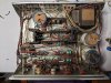
Here's a first look at the inside:
IMG_20200531_210107.jpg

Tidy and dirty! I got the original instructions, too:
Manual_front_cover.jpeg

Here's some history from the original owner:

I purchased the amp in kit form in 1969 and assembled it myself. [Oops! I just looked at the original receipts for all this stuff and it looks like I purchased all this gear in November, 1970. I was a year off!]

The amp is a Dynaco SCA-80. I remember it arriving as a Dynakit, but all the markings on it are Dynaco. For audiophiles, some Dynaco amps are gold. Their tube amplifiers leading up to this model remain highly desirable. Around 1968 or so they came out with their first “solid state” models—originally separate amps and preamps, I believe—and the SCA-80 was their first integrated (amp and pre-amp), solid-state unit. Interestingly, one of the things I strongly remember about this unit is that it still had a brief “warm up” time—i.e., it didn’t start amplifying sound until a few seconds after it was turned on. Not sure what parts had to “warm up” as I’m sitting here now…

The obvious negative of mine today is that it doesn’t work. No, I haven’t tested the transformer itself, but I know the unit hasn’t amplified sound in a long time. Probably deteriorated components. Over 20 years ago I took it into a shop—back when audio repair shops were ubiquitous—and they replaced the two main capacitors and a few small ones. The other negatives are cosmetic. 1) I dropped the unit during a move 20-30 years ago and the upper left corner of the front plate is slightly bent, though I’ve endeavored to straighten it. And 2) Some of the lettering has come off the anodized aluminum front plate and much of it off the back chassis.

But the pluses are pretty great, IMHO, especially for an enthusiast. The mere fact that there’s so much information out on the Interwebs tells me that this (and other Dynaco) units are worth investing in. But—and again, especially for your interests—this is a hobbyists dream! There’s not a single integrated circuit in this thing. Every component is discrete and easy to get to. I can send you a copy of the schematics if you’d like.
​
And the schematics were included in the package; they're in the "centerfold" of the instruction manual:
Schematic_from_manual.jpeg

And the next page has the parts list and layout of the PCBs:
Parts_list_and_boards_from_manual.jpeg
 
What's the Plan?

I did start with a simple enough plan:
  1. Take each of the big capacitors out of circuit and test them with the LCR meter. These include the power supply caps, C9 (5000 uF/80 V) and C11 (a cylinder "packed" with three caps, 700 uF/75 V, 700 uF/60 V, and 800 uF/20 V), and the output caps, the two C7's (5000 uF/80 V).
  2. Pull out the single fuse and test it.
  3. Pull each board.
    • Suck off the old solder.
    • Re-solder all joints, and re-tin all traces.
    • Test each capacitor out of circuit.
  4. Disassemble, clean, and reassemble the volume and balance pots.
  5. Clean the contacts on the selector switch.
And the results:
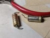
  1. None of the big caps appear faulty. All values are within +/- 20%, and the ESR values seem reasonable: all three of the big 5000 uF caps had nearly the same ESR value, 0.14 ohm.IMG_20200531_214212.jpgIMG_20200531_215244.jpgIMG_20200531_215508.jpg
  2. The fuse is fine.IMG_20200531_214608.jpg
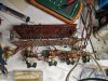
  3. Pulling the boards and soldering were straightforward. Testing revealed that a few of the electrolytic caps were out of spec. Specifically, C28 (500 uF/2 V) on each pre-amp board (PC-17) was out of spec. IMG_20200601_003431.jpg IMG_20200605_001350.jpg IMG_20200610_192231.jpg
  4. The pots cleaned up nicely with 99% isopropanol, CRC QD Contact Cleaner, 3M 3000-grit wet/dry sandpaper, and DeoxIT D5.IMG_20200613_204921.jpgIMG_20200613_205126.jpgIMG_20200613_214730.jpg
  5. Similarly, the contacts on the selector cleaned up nicely.
 
Really, What's the Plan?

At some point, the original, simple plan got derailed. I did some reading that suggested that simply "fixing" the SCA-80 was unlikely to produce an amp that I wanted to listen to.

I've worked my way through several of my old pieces:
  • I have an NAD 701 receiver that I bought new in the mid-90's. I re-capped it and touched up the traces where a few had been corroded by leaking caps.
  • I have a Pioneer PL-630 turntable (1979) that I bought used in 1984. I restored it by following Rich P's guide: full re-cap, re-solder, clean, and lube.
  • I have a Magnavox CDB 582 CD player (aka Philips CD 582; 1988) that I bought used in the mid-90's. I fixed the tray opening mechanism, re-capped it, replaced the power-supply diodes with Schottkys, and replaced most of the op-amps.
  • I have a Sansui 2000a receiver (1970) that I picked up at a yard sale in the mid-oughties. I've done a little repair work and replaced a few caps.
I thought the CD player sounded great until I finished the PL-630. And I thought the NAD receiver sounded fine with the PL-630 until I brought the Sansui back on line. Holy ****! Charlie Parker just appeared in my basement! I have an original pressing of Bird and Diz that I recently cleaned, and I also have it on CD. The CD didn't make me sit up and take notice. When I had to take down the Sansui for repairs, the NAD made me sad. Restoring the NAD was worth it for the learning experience, and it sounds OK, but the Sansui blows it out of the water. I don't need a crappy amp, if that's what a repaired SCA-80 would be; I have the NAD. I don't need another mediocre amp, if that's what a restored SCA-80 would be; I have a nice little Kinter "class T" amp that does a great job for the sound from the TV in the living room.

I've read the Van Alstine papers, the UpdateMyDynaco.com stuff, several AK threads, and a couple of blogs. Here's what I gather from my reading. Repairing the SCA-80 will produce a working, but barely listenable, amp. In order to make it good, I need to replace, like, everything and make some modifications. I've considered the UpdateMyDynaco route and decided I don't really want to go there. It doesn't seem like anything short of the full UpdateMyDynaco monty will produce a good amp, but the full UMD monty will essentially fill the SCA-80 chassis with a modern, LM3886 op-amp-based amp. I may very well want to make myself an LM3886-based amp at some point, but some combination of nostalgia, curiosity, and loyalty makes me want to see what the SCA-80 can do.

But the price tag on the components is, well, significant, so I need some convincing. I can model it! I've got some experience using LTSpice. Maybe modeling the SCA-80 circuit will tell me something. At this point, I'm going to skip to the end and tell you that I think I might've nailed it. As I write this, the fan on my laptop is howling with the strain of simulating everything from the transformer to the 8-ohm loads representing the speakers. Let's check it out.
 
I don't understand what you are trying to achieve with those strings of resistors and LT1431s. If you want to stabilize the power supply (why would you want that in the first place?) put the LT string in the output loop of the darlington so that it has to work for its money. And use only one LT1431 and use its collector to drive the darlington via a level shifter. But again, why bother?

I concur that the notion of replacing the amp with an LM3886 destroys the nature of this nice amp.

Edit: also read the comments on HiFiEngine's SCA80q page.
 
Last edited:
I don't understand what you are trying to achieve with those strings of resistors and LT1431s. If you want to stabilize the power supply (why would you want that in the first place?) put the LT string in the output loop of the darlington so that it has to work for its money. And use only one LT1431 and use its collector to drive the darlington via a level shifter. But again, why bother?

You caught me writing!

Main Power Supply (continued)

Mains AC comes in at the upper left, goes through the transformer, which I've parameterized as best I could from measurements, and then the full-wave rectifier, which is composed of four diodes. The last original part is the first big capacitor, shown here as 4700 uF (microfarads), but originally was 5000 uF. I've added a second 4700 uF capacitor to reduce the ripple some more before branching the main supply line into two noise reduction and regulation circuits, one for each channel, left and right.

Each of the latter circuits combines a capacitance multiplier with a voltage regulator. These circuits are like amplifiers that amplify noislessness. On each channel, I take an itsy bitsy little trickle of current down through the network of resistors and capacitors and use almost all of the current to power the pair of transistors in a Darlington configuration, which simply means that the output of the first transistor, on the bottom, is the input to the second. The itsy bitsy part goes through a 12th-order low-pass filter. If I were sending all or most of the current through such a filter, I'd have to use huge-value capacitors and tiny-value resistors in order to keep the voltage high enough, since there's a voltage drop across every resistor. But that voltage drop is proportional to the current, and the current is tiny, so I don't need to worry much about losing voltage across resistors. That's great, because resistors are cheap, and high-value resistors don't cost any more than low-value ones. With capacitors, higher values cost more.

So little voltage is lost in the filter that I need to drop it some more for the capacitance multiplier to work. The transistors amplify "noislessness," but only if the voltage powering the transistors is high enough relative to the output called for by the input. I want the voltage at that output to be lower than the lowest "troughs" of the ripply supply voltage. The schematic calls for 74 V, and that turns out to be low enough, but I need a shunt to get the input low enough, i.e., 74 V plus two diode drops, one for each transistor, so 75.2 V. I get that voltage with a shunt. My old Sansui receiver accomplishes this trick by using a 25 V zener diode at the base of a single transistor to give a 24 V supply to the preamp and tuner. Zeners are great, but they are sensitive to temperature. the LT1431's are programmable voltage references. Each one can only go up to 36 V, so I need three in a stack to get 75.2 V. After the shunt, then, I've got a super-clean trickle of current input to the Darlington transistor pair, which therefore produces a super-clean high-current output.

I've got two of these circuits, one for each channel, so that I don't get cross talk between channels. Even with a super-clean supply, the amplifier will put a small version of its output onto the supply rail. If I were to power both channels with the same supply rail, then each channel's output would get onto the supply rail and, hence, to the other channel. I tested that configuration, and the cross talk is real.

Anyway, here's the output of the main power supply at full load, i.e., with the volume cranked up to ten:
SCA80_Mod07_main_power_supply_output_graph.jpeg

The pink trace is the voltage probed between diodes D4 and D5. The green trace is the voltage after the two big capacitors. The blue trace is the voltage at the output for the left channel, "74VL."
 
Hate to bust your bubble but you do not have a capacitance multiplier. You just have an emitter follower (darlington). You use a string of LT1431s as glorified zener without using its advantages of actually stabilizing the output voltage for you. But again, why bother stabilizing the power supply in the first place? Provide a clean power source to the preamp and driver circuits and let the output transistors take full advantage of the available voltage in the power supply.
 
Main Power Supply (continued)

In the next graph, I've zoomed way in on the blue power supply output trace:
SCA80_Mod07_main_power_supply_output_graph_zoom.jpeg
The noisiness looks a bit wicked, but consider two things: 1) The volume is cranked to ten. Before my last round of circuit tweaking--ahem--optimization, I was getting awesome, asymmetrical clipping in the power amp stage. I'll show later that the output is going nearly from rail to rail, and there may be a little bit of clipping. 2) The magnitude of the ripple is less than 300 mV!

But why bother? Because I want an awesomely, absurdly low noise floor! I don't want any cross talk, and I don't want the mains hum to be any louder than any other noise source. Here's the spectrum of the 74 V supply for the left channel:
SCA80_Mod07_main_power_supply_output_FFT_graph.jpeg
There's a 120 Hz spike in there somewhere.
 
As for stabilized power supply, been there, done that:

100v_psu_sch.png

Then you also see why it sucks as the provocation I introduce causes mayhem...
 

Attachments

A propos LTSpice, did you happen to simulate the output amp as well? I have this nagging feeling it has a serious design flaw...
 
A propos LTSpice, did you happen to simulate the output amp as well? I have this nagging feeling it has a serious design flaw...

I did, because I had a similar nagging feeling. And it seems to have had a serious design flaw. At least, something was going seriously wrong when I turned the volume up all the way and drove it with a big enough signal at the phono input. The output was clipping asymmetrically and far short of the rails. I then did a DC bias version, where I took off the main power supply bit and fed it with a pure 74 V DC voltage source. After making sure the DC voltages all matched up with the manual with the input shorted, I disconnected the phono preamp and substituted a small-signal AC voltage source at the preamp input, and I did AC sweep and noise tests. At that point, I was able to flatten the response by playing with the values on the output capacitor-inductor pair and track down and eliminate the sources of some noise spikes I was getting at around 1 to 2 kHz. The remaining spike is ultrasonic, although none of these spikes were all that large, less than 1% for signal-to-noise, or less than 8 uV/Hz^1/2. I'll be getting there with my posts, but not tonight.

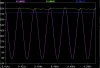
For now, though, here's a sample of the output at the speakers:
SCA80_Mod07_speaker_outputs_graph.jpeg
If you look closely, there's a little bit of clipping in the left channel (red) at the bottom extreme when compared with the right channel (green), and a little bit of clipping in the right channel at the top extreme. The signals aren't actually offset in voltage, at least not on average; rather, I've offset the phases of the lowest frequency input by 90 degrees between left and right channels.

This is with some mods: Regulated power supplies for preamp and phono preamp on each channel; TIP31C and TIP32C transistors for Q2, Q3, and Q4; MPSA18 transistors in the preamp; and MJ15003 output transistors. With the MJ15003's, the output does NOT benefit from a greater-value output capacitor; 5000 uF is exactly right. I've also changed some of the capacitor values, per Van Alstine, and I "tuned" the value of the capacitor in the Zobel network up to 220 nF (was 100 nF). All the details in time.
 
Hate to bust your bubble but you do not have a capacitance multiplier. You just have an emitter follower (darlington). You use a string of LT1431s as glorified zener without using its advantages of actually stabilizing the output voltage for you. But again, why bother stabilizing the power supply in the first place? Provide a clean power source to the preamp and driver circuits and let the output transistors take full advantage of the available voltage in the power supply.

But one more thing before I go, because I want to be absolutely clear regarding your suggestion. Are you saying that regulated power supplies on the preamp (24 V and 17.5 V) and on the power amp's driver stage (71 V) are worth implementing, but regulation on the 74 V supply to the gain and output stages is not worth implementing? Are you also saying that I should not bother with trying to reduce ripple on the 74 V supply, at least not below what can be accomplished with 5000 or 10,000 uF at the output of the rectifier? Because I could take the LT1431's or LM431's out and get the voltage lower, for purposes of a good capacitance multiplier, by increasing the resistor values from 220 ohm to, say, 470 ohms each.

Another clarification, please: When you say that I don't have a capacitance multiplier, just an emitter follower, are you objecting to my using the term "capacitance multiplier" for something that doesn't actually multiply capacitance (I know that), or are you saying that I'm incorrectly implementing the design concept that goes by that name? Quoting Horowitz and Hill:
A "capacitance multiplier" for filtering incoming dc consists of an emitter follower biased with a smoothed (lowpass-filtered) replica of the noisy input. (Art of Electronics, Third Edition, p. 579)​
FYI, I do not design circuits for a living. What I know about electronics comes largely from taking Horowitz's Laboratory Electronics course in the late 80's. For example, I did not know that an LM431 was a thing before a few days ago, when I stripped down an old computer power supply and Googled the part number on the physical component.
 
You're right, I was confused with an electronic inductor. Still, an emitter follower doesn't make use of the gain the TL431 can provide and has a finite output impedance (I believe equal to r(be)). And you are wasting a lot of voltage to make it work.

Also note that the LT1431 is a beefed up version of the three-legged TL431.

BTW- can you share the LTSpice model of your output amp? Would love to play with it to see how it performs and how to fix the serious design flaw I see in it.

Oh, and cleaned up the schematic a bit and included some component values.
 

Attachments

Last edited:
Here's a new version with more values added. What I don't get is that Q3 and Q4 don't have any bias. Eagerly awaiting the ASC file from Geomorphdog.
 

Attachments

Here's the LTSpice model for the SCA-80 with modifications. I've put the .model and .subckt directives for non-standard parts (i.e., those not included in my version of LTSpice) on the schematic. I'm including a couple of symbols as separate files. I plan to elaborate on the mods and results in later posts, but it doesn't hurt to get this model/schematic out now.

Note that I've drawn the circuits differently relative to the original schematic. My aim was to make the evolution of the signal progress from left to right and accurately represent relative DC bias points vertically on the diagram.

Here's a new version with more values added. What I don't get is that Q3 and Q4 don't have any bias. Eagerly awaiting the ASC file from Geomorphdog.

I can see from the original schematic why you say that Q3 and Q4 don't have any bias. They do, but it's hard to tell, because their emitters are biased by R17 and R16, respectively, and these resistors are located on the so-called power supply board, PC-19--"so-called" because they are the biggest things on that board, but they have nothing to do with the power supply. R16 and the diode pair, D2 and D3, also bias the collector of Q6, and R17 and R19 bias the emitter of Q5. These things are more easily recognized on my schematic, because I've drawn R16 and R17 on PC-18, the power-amp board, and I've turned the diodes, D1, D2, and D3, so that they're oriented according to their DC bias points; so, on my schematic, D1 (zener) points up, and D2 and D3 point down.

I've taken the time today to label the various elements of the schematic, so I hope it's relatively easy to follow.

As configured, the volume is turned all the way up, and the magnitude of the 20 Hz input is 2.0 mV, just big enough to clip the tips off the upper and lower extremes of the output, where the voltage swings between +/- 32.5 V, give or take 0.1 V.
 

Attachments

Very informative and interesting thread :thumbsup:
I am following along and eager to read your posts .... you have me almost convinced to take up the non-working SCA-80 from the "one-day-I-will-get-to-it" projects shelf.
Good luck & Rgds
Mayank
 
Back
Top Bottom