Dynaco stereo120a Restoration
I have had this unit for many years. The last time it was in service was about 15 years ago. As far as I can remember, it was working well. I did not test the unit before I began working because I was worried about causing damage by powering up before some capacitors had been changed.
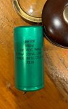
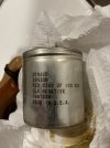
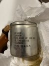
I originally planned on changing all the capacitors but due to the high price of replacing the large chassis mounted caps (C7, C9, C11, C12), I decided to change all the other electrolytics on the boards and power the unit up slowly with a dim bulb and a variac, hoping the large caps would reform and survive.
Physical:
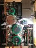
First, I began with cleaning. The unit was so grungy and rusted that I had no choice but to remove everything from the chassis. I used a metal polish to clean the chrome as best as could be expected being careful not to clean off the screen printing, cleaned all the screws, nuts, connectors, clamps, caps, boards, wires….it was really dirty. The upper painted cage cleaned up well and needed no paint.

I checked the values of all the parts to see that it matched the schematic. I used a caliper to measure all the parts that I planned to replace so I could pick proper parts to order. Then, I reinstalled all the parts in the chassis.
Electrical:
I wanted to keep the amp as original as possible and keep all the original transistors and circuit design. This amp is a piece of history. It is one of the first mass-produced solid-state amplifiers rated at 60W per channel.
I downloaded all the schematics and info I could find on the unit and compared the actual circuit to the different versions of schematics to determine which version I had. Below are some resources I used.
https://www.updatemydynaco.com/Stereo120Repair.htm
https://www.hifiengine.com/manual_library/dynaco/stereo-120.shtml
https://www.updatemydynaco.com/documents/TIPmod.pdf (I did not do the TIP mod)
https://davidreaton.com/dynaco/stereo-120/
After considering all the options from rebuilding -to- modifying, I decided what parts I wanted to change. Then, I placed orders with Digi-Key and Mouser for parts. (parts list attached in Excel format)
I removed each board one at a time to replace parts and reinstalled.
Some minor changes were made based on availability of parts and minor upgrades that Dynaco implemented in later years of production to improve reliability.
1. I changed R16 and R17 on the amplifier boards. They were poorly installed originally and were leaving burn marks in the boards. I went up in value from 7W to 8W and used a through hole type to facilitate safer heat dissipation.
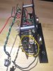
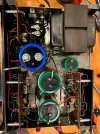
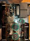
2. I raised the voltage values of some of the capacitors for fit and availability on the amp boards.
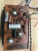 old vs new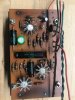
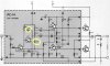
3. I changed C13 and added C15 as per Dynaco’ s last version of the amp. All the other circuit changes were already implemented by the production of my particular unit. Pictured below is what I believe is the last circuit iteration.
4. I doubled the capacitance of C10 on the Power board to slow down the initial startup charging of C12 and protect the power supply’s pass transistor. This is not necessary unless C12 is increased in capacity which I may do in the future. (Refer to updatemydynaco.com power supply upgrade section)
I will probably get replacement large caps if the amp proves to work well on initial testing (my choices for these caps are on the parts list attached). The website updatemydynaco.com has a good solution for the larger caps that is much cheaper using smaller caps wired together but I like the classic look of the larger more expensive caps.
I am also considering adding a thermistor (Amphenol CL-80) to the front end to slow down the inrush current on startup. The thermistor also has the advantage of lowering the mains voltage slightly. Current house power is about 125V which is higher than older designs call for. I will only try this after I have tested and benchmarked the amp.
First Test:
I hooked up a signal generator to the left and right inputs of the amp – output turned down. The outputs were hooked up to an 8-ohm dummy load and an oscilloscope. Power from wall through a dim bulb, to variac, to amp. The variac set to 20V for ½ hour, then 60V for 20 min, then slowly up to 115V for testing.
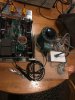
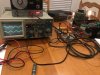
While slowly applying input signal at 1K Hz I got a good sine wave back up to about 30W (~15.5V), and then the signal would crash. The dim bulb would flash upon applying voltage to the unit as expected during the inrush current that charges the capacitors, and then go dim. As I applied the input signal, the bulbs would get brighter until the waveform would crash and then stay bright until I turned off the input signal. Then it would dim again. I started up again and tested the VDC on C12. It measured 74.1vdc which is within the acceptable range, so I figured the power supply was working ok. I removed the dim bulb from the circuit and powered up again. Without the current limiting of the dim bulb tester, I was able to get a great 1KHz sine wave at about 62 W (~22.3V) on the output. I did not push harder since that was 2W past the rating of the amp. I have no idea what output wattage would have caused the wave to distort (62W is enough from this amp). I ran the amp at 50W(20V) for about ½ hour and all was fine – she ran cool and stable. Then I hit the amp with a square wave at 50W for about 45 seconds at 100Hz, 1K, and 10K – all looked great. I did a sweep with a sine wave from 10Hz to 25KHz, and the amp seemed to be very linear. This was just a visual with an old analog oscilloscope so I don’t have numbers, just a visual check. I do not have a distortion meter, so all I can say is that the waveform seemed fine. There was no roll off on the bass end down to 10Hz and the top end had only a slight roll off after 20KHz. Amazing!
That’s all the testing I have the equipment to do - so it’s on to the speakers!
Test Equipment:
1. RCA | WA-504B/44D Audio Generator
2. ELENCO | S1325 Oscilloscope
3. STACO | type 500B Variac
4. Home built Dim bulb tester.
5. Home built 8ohm - 100W non-inductive dummy load.
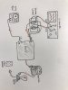 Test Setup
I'll be back to let you guys know how it sounds!
I have had this unit for many years. The last time it was in service was about 15 years ago. As far as I can remember, it was working well. I did not test the unit before I began working because I was worried about causing damage by powering up before some capacitors had been changed.
I originally planned on changing all the capacitors but due to the high price of replacing the large chassis mounted caps (C7, C9, C11, C12), I decided to change all the other electrolytics on the boards and power the unit up slowly with a dim bulb and a variac, hoping the large caps would reform and survive.
Physical:
First, I began with cleaning. The unit was so grungy and rusted that I had no choice but to remove everything from the chassis. I used a metal polish to clean the chrome as best as could be expected being careful not to clean off the screen printing, cleaned all the screws, nuts, connectors, clamps, caps, boards, wires….it was really dirty. The upper painted cage cleaned up well and needed no paint.
I checked the values of all the parts to see that it matched the schematic. I used a caliper to measure all the parts that I planned to replace so I could pick proper parts to order. Then, I reinstalled all the parts in the chassis.
Electrical:
I wanted to keep the amp as original as possible and keep all the original transistors and circuit design. This amp is a piece of history. It is one of the first mass-produced solid-state amplifiers rated at 60W per channel.
I downloaded all the schematics and info I could find on the unit and compared the actual circuit to the different versions of schematics to determine which version I had. Below are some resources I used.
https://www.updatemydynaco.com/Stereo120Repair.htm
https://www.hifiengine.com/manual_library/dynaco/stereo-120.shtml
https://www.updatemydynaco.com/documents/TIPmod.pdf (I did not do the TIP mod)
https://davidreaton.com/dynaco/stereo-120/
After considering all the options from rebuilding -to- modifying, I decided what parts I wanted to change. Then, I placed orders with Digi-Key and Mouser for parts. (parts list attached in Excel format)
I removed each board one at a time to replace parts and reinstalled.
Some minor changes were made based on availability of parts and minor upgrades that Dynaco implemented in later years of production to improve reliability.
1. I changed R16 and R17 on the amplifier boards. They were poorly installed originally and were leaving burn marks in the boards. I went up in value from 7W to 8W and used a through hole type to facilitate safer heat dissipation.
2. I raised the voltage values of some of the capacitors for fit and availability on the amp boards.
old vs new3. I changed C13 and added C15 as per Dynaco’ s last version of the amp. All the other circuit changes were already implemented by the production of my particular unit. Pictured below is what I believe is the last circuit iteration.
4. I doubled the capacitance of C10 on the Power board to slow down the initial startup charging of C12 and protect the power supply’s pass transistor. This is not necessary unless C12 is increased in capacity which I may do in the future. (Refer to updatemydynaco.com power supply upgrade section)
I will probably get replacement large caps if the amp proves to work well on initial testing (my choices for these caps are on the parts list attached). The website updatemydynaco.com has a good solution for the larger caps that is much cheaper using smaller caps wired together but I like the classic look of the larger more expensive caps.
I am also considering adding a thermistor (Amphenol CL-80) to the front end to slow down the inrush current on startup. The thermistor also has the advantage of lowering the mains voltage slightly. Current house power is about 125V which is higher than older designs call for. I will only try this after I have tested and benchmarked the amp.
First Test:
I hooked up a signal generator to the left and right inputs of the amp – output turned down. The outputs were hooked up to an 8-ohm dummy load and an oscilloscope. Power from wall through a dim bulb, to variac, to amp. The variac set to 20V for ½ hour, then 60V for 20 min, then slowly up to 115V for testing.
While slowly applying input signal at 1K Hz I got a good sine wave back up to about 30W (~15.5V), and then the signal would crash. The dim bulb would flash upon applying voltage to the unit as expected during the inrush current that charges the capacitors, and then go dim. As I applied the input signal, the bulbs would get brighter until the waveform would crash and then stay bright until I turned off the input signal. Then it would dim again. I started up again and tested the VDC on C12. It measured 74.1vdc which is within the acceptable range, so I figured the power supply was working ok. I removed the dim bulb from the circuit and powered up again. Without the current limiting of the dim bulb tester, I was able to get a great 1KHz sine wave at about 62 W (~22.3V) on the output. I did not push harder since that was 2W past the rating of the amp. I have no idea what output wattage would have caused the wave to distort (62W is enough from this amp). I ran the amp at 50W(20V) for about ½ hour and all was fine – she ran cool and stable. Then I hit the amp with a square wave at 50W for about 45 seconds at 100Hz, 1K, and 10K – all looked great. I did a sweep with a sine wave from 10Hz to 25KHz, and the amp seemed to be very linear. This was just a visual with an old analog oscilloscope so I don’t have numbers, just a visual check. I do not have a distortion meter, so all I can say is that the waveform seemed fine. There was no roll off on the bass end down to 10Hz and the top end had only a slight roll off after 20KHz. Amazing!
That’s all the testing I have the equipment to do - so it’s on to the speakers!
Test Equipment:
1. RCA | WA-504B/44D Audio Generator
2. ELENCO | S1325 Oscilloscope
3. STACO | type 500B Variac
4. Home built Dim bulb tester.
5. Home built 8ohm - 100W non-inductive dummy load.
Test SetupI'll be back to let you guys know how it sounds!