• The move to the new server is done. There are some software and database maintenance updates in process. This has us passing the hat around to help out. We appreciate any donations. Seriously, even a dollar helps. The payment page may be found here - https://www.audiokarma.org/support.html
Very nice work. I missed this thread when you first posted it.
Nice dynaco system. I'm more into dynaco tube gear myself, but if I ran across a SS Dynaco amp locally I would probably jump on it.
They produced some decent equipment at very reasonable prices.
I had a PAT4 for awhile. It was a basket case when I found it. It took a lot.of work to bring it back. I still have a FM3 tuner I restored, a Dynakit clone ST-35 amplifier, and a ST-70 with a VTA driver board. I'm keeping an eye out for a FM5 tuner for sale locally.
Thanks!
I would love to have an ST-70.
 
I have another update on this unit. I never did change the output caps and also one left on the power supply side. The amp lost a channel while on during the night. In the morning one channel was fine and the other was dead silent. I could find nothing wrong but the output cap on that channel seemed suspect while reading with a multimeter set on capacitance. I figured I would replace the two output caps and the other electrolytic in the power supply that I had not changed yet.
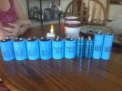
This is the cap I chose for the output caps. It's pretty close in value and exactly the same size.
1709844531493.png


As unlikely as I thought it was, it was indeed the output capacitor that was the problem causing the loss of one channel of the amplifier. There were no other components effected even though it happened in the middle of the night and kept running for who knows how long after the failure.
Now it is done and should run for years to come.

Some pics for your enjoyment:
before output caps.jpg

before/after
after output cap.jpg


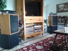
system in rack.jpg

:)
 
Something to consider… that Stereo 120 needs to breath. Stacking the PAT-4 etc impedes the heat flow away from the amp. Probably not an issue if you do not drive it very hard, but worth considering. I built the 120 in 1974, and kept it running until the early 2000s. Great amp for its time, with some issues. I highly recommend Update My Dynaco complete rebuild for modern performance. Great power supply design, amp boards.
 
I have three of these amps all rebuilt with computer grade caps, these were for the last two. The taller caps were returned for shorter, they would have protruded through the cage lol.

image-54.jpg

Used two for a number of yrs to bi-amp a pair of modified series one Heresies. They're now sitting in the closet waiting for that rainy day.

20161125_093526.jpg
 
Last edited:
This may be a dum question but why is there wire wrapped around those caps. Is it some kind of filter?
Yes. the coil is part of the circuit. It is a low pass filter in series with the load (speaker). It is there as a low pass filter to filter out very high frequencies above the audible range.
 
The coil, aka “inductor,” is also a component used by design in your speaker crossover (usually) to filter selected frequencies. The designer of the amp circuit (Hafler?) cleverly used it here for the purpose stated above.
 
Had an ST-120 long ago, probably one of my first "real" home stereo power amps that actually had some oomph and didn't glow in the dark.

It was blown up, but at that time all of the transistors were readily available from our local suppliers. Rebuilt it and was very happy and impressed with the sound. It didn't have the harsh, lifeless sound that until then had always been present with every other SS amp I had tried. Ran it (often long and hard) for a couple of years. Never had a problem.

I guess that's when I developed a weakness for SS power amps with cap-coupled outputs; I also really like Acoustic Control Corp. guitar and bass amps :)
 
Something to consider… that Stereo 120 needs to breath. Stacking the PAT-4 etc impedes the heat flow away from the amp. Probably not an issue if you do not drive it very hard, but worth considering. I built the 120 in 1974, and kept it running until the early 2000s. Great amp for its time, with some issues. I highly recommend Update My Dynaco complete rebuild for modern performance. Great power supply design, amp boards.
True. I plan to either modify the rack or find a better one for the system. It does need to breathe.
 
It is there as a low pass filter to filter out very high frequencies above the audible range.
Which also means the amp can oscillate like crazy but not show up on the outputs. But it will either run very warm or blow up. So best to scope the outputs before the final cap/inductor, after any rebuild. Had this happen on an SCA-80Q after doing a TIP mod. It has an amp section very similar to the ST-120.
 
Which also means the amp can oscillate like crazy but not show up on the outputs. But it will either run very warm or blow up. So best to scope the outputs before the final cap/inductor, after any rebuild. Had this happen on an SCA-80Q after doing a TIP mod. It has an amp section very similar to the ST-120.

I had not thought about scoping before the cap/inductor. Makes sense.
I had wondered if the suppression of HF on the output could somehow help keep the stage before from oscillating by effectively increasing the load for higher frequencies. I am not sure if this effect exists. I also wonder if the coil is really more about flat response within the audio range than very high frequencies. One would think that HF oscillation would be addressed before/within the output section.

I think I will scope before the cap/inductor as a rule when bench testing this topology after reading your comment. It makes sense to me. Other ways to check for this include watching the temperature on the OTs and checking the power draw with no input signal. A scope is better but, if you don't have one, these methods will provide clues that HF oscillation may be occurring.
 
I did a cursory rebuild last year as I had mentioned in an earlier post.
It was ok until the PS decided to go into fold-back mode and I gave up on it.
I recently did the UpdateMyDynaco kit with it.
Still looks the same from ten feet away but dang, it performs flawlessly.
 
Which also means the amp can oscillate like crazy but not show up on the outputs. But it will either run very warm or blow up. So best to scope the outputs before the final cap/inductor, after any rebuild. Had this happen on an SCA-80Q after doing a TIP mod. It has an amp section very similar to the ST-120.
C8 and R18 on each amp board output, which are mounted on the chassis right at the output binding posts, help to keep any high frequency signals above suitable listening frequencies from getting to the speakers, but it also may smoke the resistor if things get well out of hand. Checking for proper values and function of caps C13, 14, and 15 will also help to insure the amp doesn't oscillate. The TIP's on your SCA-80 most likely have a higher Ft - bandwidth, which is probably why you had that experience, and also may happen if replaced on a older ST-120 that didn't have all of the mod done already.
 
I have another update on this unit. I never did change the output caps and also one left on the power supply side. The amp lost a channel while on during the night. In the morning one channel was fine and the other was dead silent. I could find nothing wrong but the output cap on that channel seemed suspect while reading with a multimeter set on capacitance. I figured I would replace the two output caps and the other electrolytic in the power supply that I had not changed yet.
This is the cap I chose for the output caps. It's pretty close in value and exactly the same size.
1709844531493.png


As unlikely as I thought it was, it was indeed the output capacitor that was the problem causing the loss of one channel of the amplifier. There were no other components effected even though it happened in the middle of the night and kept running for who knows how long after the failure.
Now it is done and should run for years to come.

Some pics for your enjoyment:
before output caps.jpg

before/after
after output cap.jpg


system in rack.jpg

:)
Looking at your pics of the C7 cap replacements, and the 2 amp boards, I don't see any TO-220 cased TIP transistors. I guess if it's behaving OK, that's a good thing but if you ever wanted to do it, look for a owners manual download that has the TIP transistors listed in the parts list, and it will also have all of the other needed component changes and additions. One more thing to keep in mind is, C1 on each amp board is a low voltage tantalum cap, and over time those can develop leakage / parallel resistance, and it would also be a good idea to replace them with like components, or a equivalent value film cap. The actual Dynaco TIP mod file is still available at the Updatemydynaco site, I tried uploading it here, but it's too large a file for the server apparently , so a link is here--> https://updatemydynaco.com/documents/TIPmod.pdf If you do it, you will need to source, or fabricate 4 heat sinks for TO-220 transistors, as the cheezy ones in the kit are no longer available.
 
Last edited:
Yes. I never did the tip mod to the amp. I have the documents in a file but I figured I would keep the original transistors as long as they work. I also did not change C1. Hard to remember, it was a while ago. I don’t think I even knew it was a tantalum. I just went for the electrolytic and the last changes Dynaco made to the circuit before the tip mod.

My next move on this system would be to work on the preamp as the phono stage really sounds bad. The aux input is good enough for now.

My main system is on the fritz, so I am listening to the Dynaco right now! Sounds great.
 
Back
Top Bottom