• The move to the new server is done. There are some software and database maintenance updates in process. This has us passing the hat around to help out. We appreciate any donations. Seriously, even a dollar helps. The payment page may be found here - https://www.audiokarma.org/support.html

Dynaco ST-120 Unopened Kit

They're getting to be 40+ years old. Depending on how humid the environment, they can have absorbed water, cracked from brittleness of the casing - that sort of thing. What I've found on old tube amps is that just flexing old resistors causes hairline cracks, too. This creates sizzling sounds or elevated noise floor in the amp. The underlying assumption, here, is that the buyer wants to have the kit-build experience of this specific model amp. For some of us, that's a been-there-done-that sort of thing. I'd want a reliable product when I'm done.

The materials technology for resistors and caps has come a _long_ way in the past 4 decades. Why not take advantage of it? Otherwise, build the kit and then chase down the gremlins or just admire it as an unfinished kit for the collector of such things.

Cheer,

David
 
It depends on whether this unit is mainly to restore a bit of history or if it is to be a "daily driver". If built as original, one would only want to run it to show it off. If it is to be a daily driver, then, as Conrad recommends, many parts should be replaced.
 
If you are considering using this on a regular basis, consider doing the TIP mod. It will add stability and reliability.
One version of the TIP mod I've seen recommends replacing 2N3055 outputs with 2N3772. Not sure which you have The 2N3772 are getting harder to find, and if you do they won't be the Dynaco 'red dot' screened version. I've seen the OnSemi MJ15003G recommended as a more robust modern replacement for the outputs.

Cool project. I'd love to find a NIB unbuilt kit.
 
My understanding is that Dynaco used selected 2N3055 transistors and also needed the regulated power supply because an "off the shelf" 2N3055 was not rated for the voltage used. Go beyond the now outdated MJ13xxx and use MJ21194 or MJ21196. SOA is much better and there is less beta droop at peak currents. You could then remove the regulated supply and run the unit directly from the main power supply. The regulator is not needed because the power amplifier itself is the regulator for the output. The regulator was only needed due to the output transistor voltage limitations.
 
Thanks for the comments and tips.

I ordered a variable DC power supply to form the caps. It's a cheap one, so I will be careful using it. While waiting for it, I have been considering the role of this amp. It will see some use, possibly for surround. I will likely crank it up now and then on 8 ohm speakers.

I know about the TIP mod, and a couple of minor changes made in the two later revs. Those might happen later.

I have a 120 of the same rev that is all original and sounds like new. I am curious to see if this one will play the same. It would not bother me to do needed component replacement later.
 
Some time in the seventies I was in the hifi business when Dynaco went belly up. The sales rep showed up with a trunk full of Dynaco kits. Sadly no ST 70s or mark IVs but he sold me a ST 120, a PAT5, and a FM5 for just over $100. I built them used them for a short period, didnt like them, and sold them for a large profit. Really wouldnt want them back. Shortly after Hafler came out with the DH200 kit then Adcom and that changed the landscape of the Amp field forever.
 
I've been testing caps as time permits. All good so far. I had a 3k resistor handy. The voltage across it with the 3300uf/100v cap dips below 200mv within a couple hours. The other big ones are good also.
rps20170211_171645.jpg
I grabbed an old 3300/60 from a non-working ST-120, which had previously tested out as a 0.19 ohm resistor. With the supply set to 60v, nothing happens, it takes no charge, as expected.
rps20170211_171515.jpg
I pulled one side of the 50/40 electro on the PS board, and it looks good. I need to check all the ones on the amp boards. I think I will check a couple random resistors and if they look good, proceed with the build.
rps20170211_171419.jpgThis cheap power supply seems to work well for this. You can limit current, and I have it set to 100ma. Of course the resistor limits current, but it's a nice feature.
 
Yep, that's a time capsule! At least it is going to someone who would appreciate it - nice! If you're planning to construct it, by all means document it if you have the time and inclination.

I'd suggest, however, that you plan on replacing the electrolytic caps. They're at least 40 years old and will have likely dried out inside in that time. Measure the resistors before mounting then, too, to be sure they've not drifted as well. Use fresh solder, too.

Enjoy!

Cheers,

David
Agree.....This is what the Caps look like inside:

MONH.jpg
 
Assembly commences.

All the electrolytics and a sampling of resistors test out fine, so I will give them a chance to live. All I have done so far is the feet, RCAs, binding posts, and cap clamps. I placed the caps briefly to test the fit. This is fun!
rps20170218_211016.jpg rps20170218_211053.jpg rps20170218_211210.jpg rps20170218_210900.jpg rps20170218_210840.jpg

If all the old stuff works, the amp will he called Flight 19, and the first thing I will play on it will be The Five Tones from Close Encounters.
 
I decided I'd better test my test setup, so I am ready when the 120 is finished. I am doing FTC preconditioning (more or less) on an amp I made with LJM MOSFET boards and lots of heat sinking. This has been my main amp for a while.

rps20170219_085950.jpg rps20170219_085831.jpg rps20170219_090645.jpg

If I call this a 100wpc amp, 1/3 of that into 8 ohms works out to about 16v out. It's been going about 30 min so far. The scope is on the 100w scale. The power resistor packs are rated 180w and they are hot. The amp heatsinks are warm. Lookin' good so far.

If the 120 passes initial voltage checks, I will probably run it at 1w for a while, then bump it up to about 15 for a few minutes. If it lives thru that it will be in great shape.
 
I have one of those MCS tv/monitor/scope watt meter. The one I found had NASA calibration stickers with dates on it along with a sticker with "launch pad 6" on it. used as a closed curcuit monitor for the launch pad I guess. I want to recap it and make what ever adjustments needed but cant find a repair manual.
 
I have one of those MCS tv/monitor/scope watt meter. The one I found had NASA calibration stickers with dates on it along with a sticker with "launch pad 6" on it. used as a closed curcuit monitor for the launch pad I guess. I want to recap it and make what ever adjustments needed but cant find a repair manual.

I bought mine new and think I have the owners manual but that probably would not help.

I think Larry Klein of Stereo Review had one that was in the background of the photo for his column.

Edit: Would NASA calibrate a 5" monitor? Or could they have used it for some kind of measurement?
 
I bought mine new and think I have the owners manual but that probably would not help.

I think Larry Klein of Stereo Review had one that was in the background of the photo for his column.
Is It normal for the screen to roll up or down when in scope mode? I cant get mine to stay stable and not roll.
 
Is It normal for the screen to roll up or down when in scope mode? I cant get mine to stay stable and not roll.

It seems to roll if you don't cherry-pick an appropriate frequency. No frequency scaling. Maybe that's what you mean?
 
It's hooked up and playing mono FM talk radio for a sound check. Running a pair of ADS 200s. These are currently my main speakers, with subs. Here's a rundown of recent steps.

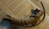
I think the pic below is important. The power cord not only looks new, it is still soft and flexible. I think being unopened in what must have been favorable conditions might have helped everything come through in good shape, including caps, resistors, etc.
rps20170225_175530.jpg
Here's a shot prior to mounting and finishing connections on the 3 boards and heatsinks.
rps20170225_175853.jpg
Nearing completion, I managed to restrain myself from initial power up long enough to make a dim bulb tester. I wasn't sure what bulb to use, tried 200w. I first tried just the power supply. Held my breath and flipped the switch. It came on.
rps20170225_175344.jpg
The bulb did not light at all. PS voltage at about 76, a bit higher than nominal 72. Repeated with one amp channel connected, then the other, then both, then direct without the DBT, and finally with a pair of test speakers. Minimal hum and hiss. DCV at 76 throughout. Moved it into the main system where it's playing now.
rps20170225_175220.jpg
I can hear just a bit of hum and hiss with my ear right up to either speaker. Nice! I had to work half a day this morning, but it's been a productive day. This amp is currently 100% stock and original except for some Thermalcote II applied to the heatsinks prior to mounting. It might very well stay that way for a long time. Music tests after dinner!
 
The dbt should probably be a lower wattage bulb because the bulb drops voltage and limits through put. Using a 200 watt bulb is fairly high voltage. That long stored amp might have liked to be brought up to voltage slowly to allow the caps to reform. Start with a low wattage bulb and give it 10 minutes repeat a couple times on the way up to a 100 or higher watt bulb.

You can check the voltage allowed with different bulbs in the dbt to learn more about the voltage drop based on bulb used.

Looks nice. Probably a better build that I accomplished in 1970 but what the heck, mine worked and hope yours does as long as mine did.
 
Back
Top Bottom