
• The move to the new server is done. There are some software and database maintenance updates in process. This has us passing the hat around to help out. We appreciate any donations. Seriously, even a dollar helps. The payment page may be found here - https://www.audiokarma.org/support.html

Dynaco ST70 low bias - help needed

Hi all - I opted to replace the output tubes as well with KT77s because I couldn't get the bias up to 1.56V target, and left channel wouldn't come up in volume until I really turned up amp and let warm up for at least 30 mins. They were old as well - Sylvania Realistic Lifetime 6CA7s.

That low volume left channel issue appears to have gone away, but still can't bring the bias up past ~1.4V before I hit the limit on bias adjusters. Any thoughts on what might be driving this? I can grab more measurements if needed.

Thanks
 
Hi all - I opted to replace the output tubes as well with KT77s because I couldn't get the bias up to 1.56V target, and left channel wouldn't come up in volume until I really turned up amp and let warm up for at least 30 mins. They were old as well - Sylvania Realistic Lifetime 6CA7s.

That low volume left channel issue appears to have gone away, but still can't bring the bias up past ~1.4V before I hit the limit on bias adjusters. Any thoughts on what might be driving this? I can grab more measurements if needed.

Thanks
Hard to say, the bias supply was factored for EL34s.
 
Check the bias circuit resister values. If the bias circuit resistors all measure good, then it could be the quad cap. If the output tubes aren't getting the correct voltages they won't bias properly. Verify your DC voltages match the ones in the Dynaco instruction chart. Also if you have a way to measure capacitance you could check the quad cap values. Remember high voltage safety.

Bill
 
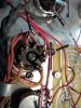
I would recommend the upgraded yellow sheet mod at the present last page of the big base line test stereo 70 thread. Looks like this, with four 1N4007 diodes and the red jumper.
20210303_090156.jpg
 
Hi all - I opted to replace the output tubes as well with KT77s because I couldn't get the bias up to 1.56V target, and left channel wouldn't come up in volume until I really turned up amp and let warm up for at least 30 mins. They were old as well - Sylvania Realistic Lifetime 6CA7s.

That low volume left channel issue appears to have gone away, but still can't bring the bias up past ~1.4V before I hit the limit on bias adjusters. Any thoughts on what might be driving this? I can grab more measurements if needed.

Thanks
Reading the thread, it seems that the Se is replaced with a Si diode. This rises the negative voltage ( and might cause the pots out of range) making it impossible to increase tube current to the 1.56 V.

If you look at the schematics you find the bias pots, gollowing from the diode there is a cap and a 10k resistor ( A). Then comes the bias pots, and a second 10k resistor (B) to ground.

reducing the (B) resistor ( parallell with another 10k or replacing with a 4.7k ) will make the bias adjustable.
Before this modification, turn the bias pots to minimum current as the current may be dangerously high if left
in the current position when powering on after resistor change.

As you use KT77 you should also replace the 270k resistors connected to eyelet 6 and eyelet 21 to 150k , this to reduce the risk of current avalanche ( redplating).
 
I've read that about the silicon diode and the bias resisters needing adjustment. I have not experienced it myself. With a silicon diode in place and the standard 10K resisters I get correct bias at mid pot range. This was true for the stock pots and a pair of new 10K replacement ones. So as with all troubleshooting suggestions, somethings gonna apply and fix the problem.
 
I dont know if it makes a diierence, but it appears your coupling caps are 1uF. Stock is .1uF IIRC. There is also looks to be one extra resistor on the bias terminal strip, not matched on the other half of the circuit?
 
I had a problem with not being able to bias my 6CA7s low enough and Kevin at Dynakit Parts recommended something like this. I believe DG suggested this as well, over in the Baseline thread but I can’t remember the details. If anybody wants to dig, it was maybe November 2019.
IIRC, it is intended to expand the range of adjustment.
My amp has an extra resistor in there, new pots and the SE has been replaced and biases fine with EL34s who knows?
Regardless, remove that blue resistor and see if it will bias.
 
What is the value of the extra resister, or what is value of resulting pair? Maybe it is grossly off what is needed. I have no trouble with the stock values and the Si diode.
 
If you’re asking me I don’t know and don’t want to open it up to find out.
Since Mr Miller is still checking in, I’m curious to see how this plays out.
 
I replaced the board in mine with a new populated 6CG8 board and found both carbon comp resistors on the quad cap (also replaced with upgrade) out of tolerance. Those probably wouldn't affect bias, but check them anyway.
 
I can’t read the value in photo.
OP has an issue where the bias is to low and can’t be adjusted high enough. dmag points out a non specified paralleled resister on the bias supply voltage divider. I know what I would be investigating at this point.

A fix put in place to correct a non existing issue can become an issue of its own.
 
Went back a read what Dave had suggested, he recommended a 22K resister paralleled there if some additional bias voltage was needed. That is why I asked what the value of the paralleled resister is. It isn't a 22K, it doesn't have two red strips.
 
Back
Top Bottom