• The move to the new server is done. There are some software and database maintenance updates in process. This has us passing the hat around to help out. We appreciate any donations. Seriously, even a dollar helps. The payment page may be found here - https://www.audiokarma.org/support.html

Dynakit ST 70. A Restoration Journey

Not a certified tech, but I have some comments.

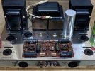
First, that is a really clean Stereo 70. (Can we get a pic of the underside?)

In my experience, 7199 tube testing can return some tricky results. I wouldn't toss those tubes or go to a new board and/or 6GH8As based just on those failing the grid leakage test on your tester. I would get a second opinion.

Original Dynaco labeled EL-34s are kind of on the valuable side. If 3 out of 4 are good, I would a) search the bay for a replacement for the bad one or b) if you want to start over, sell the 3 goods ones for a small fortune and buy modern new ones.
 
At some point adding the yellow sheet mod would be a good idea.
The sec8nd post shows the original. But there is also the other adding two more diodes.
Thank you! I hadn’t seen this yet. For now I’m going to stick with the tube. Some people rave over tube rectification and I‘d like to hear it. I do like the idea that this mod keeps the soft start. That is necessary for me because a turn on thump will make my wife think it’s junk. LOL!
 
Yes Pio 1980. That is the thread I was talking about that has set me on the course to “Restoration“ rather than “Modification”.
 
Mark

Here's hoping others will chime in and offer up an explanation on why the tubes would be testing like you mentioned.

As to the 5AR4 keep it, they're not hard to come by but as you mentioned if it aint broke don't fix it
Thanks Dswankey! I too hope others will chime in.
Rest assured the 5AR4 is staying. I really want to hear this thing as designed first. Down the road I may change my mind, I will leave those decisions for, Down The Road…
 
Not a certified tech, but I have some comments.

First, that is a really clean Stereo 70. (Can we get a pic of the underside?)

In my experience, 7199 tube testing can return some tricky results. I wouldn't toss those tubes or go to a new board and/or 6GH8As based just on those failing the grid leakage test on your tester. I would get a second opinion.

Original Dynaco labeled EL-34s are kind of on the valuable side. If 3 out of 4 are good, I would a) search the bay for a replacement for the bad one or b) if you want to start over, sell the 3 goods ones for a small fortune and buy modern new ones.
We’ll Jalousie, sadly, I got a little carried away with my cleaning. Little did I know that even just a dampened rag would wipe the silk screening right off the tube! Crap! I do have a short video that shows they said “Dynaco” but they don’t anymore. Live and learn. Besides, I can’t sell something I know to be of questionable quality.

As for the 7199’s. Yes! I will keep them. I’ll also order up a pair of the 6GH8A’s to have them on hand. That way I can swap one for the other during my first listening tests and try to make a determination as to weather or not the 7199’s are any good.

Thanks, and here’s hoping for more input. Mark
 
The life test usually drops the heater voltage, and the idea is that a really healthy tube won't drop off emission at lower voltage. Part of this assumes that the heater is already running at nominal voltage before dropping though, so it would be worth confirming that before putting too much faith in what that test has to say.

the other thing is that tube testers don't run tubes at normal working voltages and current, and emissions testers in particular aren't great for testing power tubes. The most sensible way to really functionally test these is to pop them in the amp and do a power output test. If it makes a solid 30 watts per channel, they are fine. Weak tubes will not make full power. I've got a set of absolutely whipped to death 6CA7 tubes (its an EL34 equivalent) that won't make more than about 5 watts. The same amps with good tubes make an honest 40 watts. I don't remember how they test on the tube tester.
 
Rest assured the 5AR4 is staying. I really want to hear this thing as designed first. Down the road I may change my mind,
Good.
To my way of thinking there is value in hearing the original circuit. Lots of time to hot rod it after you are familiar with its sound characteristics. Heck you may even get another one to upgrade and leave this one stock (ish).
You found a nice one. Have fun on your journey.
 
Thank you! I hadn’t seen this yet. For now I’m going to stick with the tube. Some people rave over tube rectification and I‘d like to hear it. I do like the idea that this mod keeps the soft start. That is necessary for me because a turn on thump will make my wife think it’s junk. LOL!
You still use the tube.
 
Thank you! I hadn’t seen this yet. For now I’m going to stick with the tube. Some people rave over tube rectification and I‘d like to hear it. I do like the idea that this mod keeps the soft start. That is necessary for me because a turn on thump will make my wife think it’s junk. LOL!
Unlike Solid State or some tube rectifiers, 5AR4 is a "slow start" rectifier...it takes some time before it begins to conduct. There should be no turn on "thump".
 
shouldn't be any with solid state rectifiers either. At least I've never had a thump, bump, fart, or burp out of any of mine. The output tubes are not instant-on.
 
Unlike Solid State or some tube rectifiers, 5AR4 is a "slow start" rectifier...it takes some time before it begins to conduct. There should be no turn on "thump".
Unless it is occasionally coming from the power transformer. Then its an effect of the random magnetic state of the PT at turn-on, which a surge suppressor likea CL-90 or two in the pimary circiit of the Stereo 70 can alleviate.
 
If B+ hasn't yet developed, I don't see how a turn on thump is possible with a 5AR4 rectifier. The output tubes aren't conducting yet.
I think the only way is if there's a rapid off/on cycle and there's still a charge left in the capacitors.
My 2 cents....


1691792346502.png
 
I've been told that it can occur because of the magnetic state of the core vs phase polarity of line supply @ turn on, regardless of load status.
 
Are you hearing a thump thru the speakers or a thump in the power transformer? THe latter can happen if you hit the power switch just at the right point in time the AC line is hitting a peak. A NTC thermistor in series with the power transformer primary will solve that.
 
The only reason I mentioned a “Turn on Thump” is because I believe dcgillespie mentioned it in his write up.
He switched to solid state rectification while doing his measurement. From the way I read it, he concluded the 5AR4 did its job admirable as long as the amp wasn’t pushed too hard. Keeping in the “Restoration“ spirit, the stock rectifier will stay for now.

If no one else has any tube recommendations, after some coffee, I’ll move on.
 
I just finished a pair of MK IV's with new boards replacing the 7199. Moving to the 6GH8/6U8 instead.

Using all Mullard tubes the only vintage ones being the 6U8's. No thump on powering up/down noticed during operation.

The new production Mullard 5AR4 and EL34's are working out great!
 
Moving on. Capacitors?

As requested, a shot of the underside.
9238CC94-CD74-422F-A644-9C39BC8FB902.jpeg
All the wiring looks pretty nice to me and seems to follow the pictures in the assembly manual. Let me know what you all think.

Lets start with these two caps.
6AB910D4-D7D4-4798-977E-92DCA6570FB7.jpeg
50uf @ 75 volts I believe. As noted, the assembly manual is a “Paint by Numbers” kind of thing. Certainly no information as to why this goes there and that goes here. I can’t even find these or any capacitors in the schematic provided with the assembly manual. From the line drawing I can see the negative side is wired to pin 1 on the bias potentiometers and the positive side to pin 3. I guess they have something to do with the bias circuit.

Can someone please help my understand what they do?

While doing my research I’ve seen photos of 47uf and 100uf in this position.

I’m thinking these are so old they prolly need to be replaced. What do I use and why?

The Multicap.
93629595-F1CE-4069-B4FE-F72E712D892A.jpeg
I read that most replace this with the higher capacitance one that is readily available. Should I?
I also think I read in dcgillespie’s thread something about an alternative wiring scheme. Although I could just not have understood what the poster was trying to say.

Any thoughts or recommendations on these two components will be greatly appreciated!

I’ll get to the caps on the driver board after these questions are answered.

As always, Thanks. Mark
 
Those capacitors are part of the power tube bias supply. You would do well to replace them. There is also a selenium rectifier in the circuit that should be replaced with a diode.

https://www.dynakitparts.com/product-category/dynakit-products/bias-kits-parts/

The can cap. I used the larger capacity one, but I wasn't doing a restoration with mine. That can cap houses the filter caps for the circuit's B+ supply. Your choice, but if you're really going for an authentic resto, maybe go with the original.

https://www.dynakitparts.com/product-category/dynakit-products/capacitors/
 
Back
Top Bottom