• The move to the new server is done. There are some software and database maintenance updates in process. This has us passing the hat around to help out. We appreciate any donations. Seriously, even a dollar helps. The payment page may be found here - https://www.audiokarma.org/support.html

Dynakit Stereo 70 - My Introduction to Tubes

The L-pad merely attenuates the speakers by bleeding off power.

Placing a resistor of 470 Ω across the output terminals protects against the output transformer arcing because of a disconnected speaker.

A better way to test the amplifier without using speakers is with a dummy load. Use a number of high-wattage resistors in parallel to yield 8 Ω.
 
Thanks guys. I'll stick with an original spec multi cap and continue use of the current choke after verifying it's good and cleaning it up. Now just to get a parts list together, and I should be good. I'll check into a dummy load as well. Whoever assembled this amp did a decent job. The wires are in the same locations as in the diagrams. Soldering looks good, though terminal strips never seem to look neat and tidy like circuit boards generally do.
 
Nice score! ST 70s are great amps.

Try swapping the tubes from channel to channel to see 8f the noise follows, if 8t do3s, you’ve got a flaky tube.

If you’re going to keep it, yes, recap the entire amp. Use good quality caps throughout. While you’re at it swap out all the resistors as well. Keep all the same values, just use good quality components.

You should also replace the selenium rectifier (google it) with diodes as it is a piece that often fails.

If you can post a pic with the bottom cover removed! Let’s see what it looks.ike under the hood.

Don't do any rebuilding until you solve all the problems it now has. You need to have a good starting point.
 
David, I would recommend reviewing Adam's thread mentioned above for your rebuild. http://www.electronixandmore.com/adam/dynaresto.html

This is not to discount the above discussion, but I found Adam's restoration page worked for me when I got my ST70 years ago when I was quite inexperienced with tubes.

Absolutely. I've read over that page a couple times. It's definitely helping.

Don't do any rebuilding until you solve all the problems it now has. You need to have a good starting point.

Removing and reinstalling the tubes resolved the noise issue. After that, the amp sounded really good.

Thanks
 
Just to update... caps, resistors, diodes, etc have been ordered. I'm sure that once I get started on this project, replacing all these components won't be all that difficult. Still, I always have a fear of connecting something incorrectly, reversing a cap or diode, etc and damaging something. This will definitely be a situation where I take lots of pics, refer to the manual and pics online, and make notes.... and ask lots of questions!
 
Just to update... caps, resistors, diodes, etc have been ordered. I'm sure that once I get started on this project, replacing all these components won't be all that difficult. Still, I always have a fear of connecting something incorrectly, reversing a cap or diode, etc and damaging something. This will definitely be a situation where I take lots of pics, refer to the manual and pics online, and make notes.... and ask lots of questions!
Pretty much the only components you have to worry about connecting in reverse are the silicon diode and electrolytic capacitors in the bias supply. Resistors and film capacitors generally don't care which way they're wired in; some small-signal capacitors have a line on them indicating 'outer foil', but getting this right generally isn't crucial in a tube amp. Just take it slow, double-check your wiring, refer to the schematic and other info sources as you go, and you should be just fine. :) Once again, good luck!
-Adam
 
Film capacitors deliver a performance difference depending upon how the outer foil and inner foil are connected, and the printed label on the case is often done at random and has no value whatsoever. (See the video below listed.)

It is better to connect the outside of the capacitor foil to the low-impedance side (previous stage's plate) to act as a shield. The grid side is very high impedance, so it's best to pull the signal from the interior of the capacitor as it is better shielded.

Here's a tester you can easily build, which not only will identify the shield end but it proves that manufacturers randomly label capacitors:
 
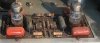
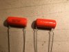
I received parts yesterday, so I'll be working on this project some this weekend, I hope. One thing I wonder about... the orange drop caps I ordered / received do not seem to have a polarity on them, while the originals I'll be replacing appear to. Are these the wrong caps?
Driver Board.jpg Orange Caps.JPG
I appreciate any help and / or suggestions!
 
I received parts yesterday, so I'll be working on this project some this weekend, I hope. One thing I wonder about... the orange drop caps I ordered / received do not seem to have a polarity on them, while the originals I'll be replacing appear to. Are these the wrong caps?
View attachment 1413841 View attachment 1413842
I appreciate any help and / or suggestions!
Those new capacitors should be fine. As I said above, film capacitors don't have a true polarity like electrolytics do, but some of them have a line indicating which end indicates 'outer foil'. You could try building a tester as Retrovert stated above to find out which end is which, but frankly, I don't think it's truly critical for this sort of application.
-Adam
 
I received parts yesterday, so I'll be working on this project some this weekend, I hope. One thing I wonder about... the orange drop caps I ordered / received do not seem to have a polarity on them, while the originals I'll be replacing appear to. Are these the wrong caps?

I think you mean the shield end is not marked. Those are film capacitors so non-polar hence no polarity marking. Your original had no polarity marking, either, but it did have a shield marking.

As the video will demonstrate, the shield marking is deceptive and fictitious because it is apparently randomly applied. A scope will identify the shield end as per the video.
 
Ahh, looks like Adam and I simultaneously posted.

To respond to the issue he raised, summarized, "does it matter?", the answer, summarized, is "that depends".

The shield will help minimize noise because of the high-impedance/low-impedance distinction.

There's a lot of noise in the amplifier: internal noise from diode Qrr broadcast and tank circuits combined with external noise from SMPS, lighting, and stray RF, some of which comes in on the input cables. The high-impedance grid is very, very good at rectifying such noise. This will generally not be audible, except AM radio is sometimes demodulated by the high-gain phono stage, but it will reduce the amplifier bandwidth because the signal is being amplified. Just like oscillation is amplified and uses bandwidth, even if one can't hear it.

Tubes are very, very good amplifiers and will happily amplify inaudible signals from the hundreds of kHz to the many tens of MHz. So one must go looking for the noise with an oscilloscope to see the effects.

My view is build for minimal noise wherever possible because it adds up. So lower-noise metal film resistors, snubbers on low-Qrr diodes, snubbers on transformers, etc.
 
What you have in there now are not the caps that came with the amp. The original caps, back in the day, were electrolytic caps and had a very definite polarity. What you have purchased are film caps and do not have a polarity. What is in the board in your photo look like film caps that have a line that is supposed to show the shield end, though as that video demonstrated, it doesn't always. Assuming you have an oscilloscope, you can fine the shield end of the new ones to install them for reduced noise. If you don't have a scope, just move forward anyway as the difference will be relatively small if you get it reversed. Rest assured, that any installation polarity will be an inprovement of what Dynaco originally supplied back in the day.

Good Luck

Shelly_D
 
Update - I finally had time to work on the amp last night. I got almost all of the underside stuff replaced - caps, a few resistors, and rectifier. It took me a bit of time removing solder from some of the old terminal strips. The 'kits' that I bought included new terminal strips, but some of the original wires were short enough that I didn't want to cut them. At any rate, with much labeling of wire locations, pics, and diagrams, I believe it's correct! Next up will be the replacing the multi cap, two caps on the driver board, and some resistors.
None of this has been particularly difficult so far and was actually pretty fun. The only scary part will come when all this is finished - powering it on!
 
Back
Top Bottom