• The move to the new server is done. There are some software and database maintenance updates in process. This has us passing the hat around to help out. We appreciate any donations. Seriously, even a dollar helps. The payment page may be found here - https://www.audiokarma.org/support.html

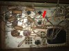
Early 1950's RCA console

The ceramic/cement squarish components are big resistors... round wax covered parts are caps, silver/aluminum cans on top of chassis are also caps... Read thru the link just posted for some basic info,,, It will help you ID parts and better understand answers to your questions...
 
Be safe! DANGER HIGH VOLTAGE. If your in over your head then please read up on the safety procedures for discharging the caps before "cleaning" yourself to an early grave. That said, what a fun looking project.
 
Be safe! DANGER HIGH VOLTAGE. If your in over your head then please read up on the safety procedures for discharging the caps before "cleaning" yourself to an early grave. That said, what a fun looking project.
Oh no, there are Dangers involved? thanks for the warning. I will read up on the link items before removing anything. I'll diagram it all before I remove parts. Thanks
 
Also, keep in mind that the electrolytic caps are polarized,,,, meaning they have to be installed one way only... make sure to note polarity when you get to diagram drawing... They also hold the charge (as do the others) after the amp is turned off/unplugged)... Google "safely discharging capacitors" for more info...
 
This link will help you on identifying and replacing all of the old capacitors.

https://www.antiqueradio.org/recap.htm

Once again, Great link.
I have read what seems like pages of information. Looks like I have about 8 different capacitors to try to match up with new ones. Matching them up old to new will be the hard task for me. I have read his information. But once I get to what I think are correct I'm going to need some validation from the pros before I start work.
One side question It made be a little OCD or the fact that I have seen several great layouts where it looks like a human has laid out a perfect system of what elements need to operate rather that what looks like someone pullout a bunch out of their pockets threw into a metal box and glues it all together and it worked.

Basic question is can I straighten it all out causing the use of longer wires, or stick to what is seen but with new components. (picture in comment #14)
 
Moving the wiring or components will lead to hum/noise in the amp,,, for instance, when you replace power supply caps, make sure the ground leads are connected to the same place they are originally...
Get it running properly before making any mods...
 
Moving the wiring or components will lead to hum/noise in the amp,,, for instance, when you replace power supply caps, make sure the ground leads are connected to the same place they are originally...
Get it running properly before making any mods...
So the length of the connected wires to the components would/could cause lower quality or other possible problems. ??
 
depends on where it is in the circuit and where it is in the amp. Basically unless you have solid reason to do otherwise, connect things to the same place they were originally. Lead dress and component placement can get to be a pretty deep topic, but without getting too far down the hole the factory layout worked 50 years ago and will continue to do so.
 
Isn't that the RS-177 amp ?

Looks like the EL84 in the middle has had a rough life.

Starrett rule, well done.

Sure looks like it. I've owned a few RS177s. Pair of 6CG7/6FQ7s, four EL84/6BQ5s, 5U4 rectifier.

This reminds me- I customized one for stand-along use (stripped and prepped the chassis, made a custom brushed aluminum faceplate, added another preamp tube to make it an integrated, and painted the entire chassis "RCA red"). A friend of mine bought it- on the condition that he would send me pictures of it (he wanted to take it home before I could take pictures). I still need to get him to take some pictures of it!

Regards,
Gordon.
 
Last edited:
I had an old Silvertone that I got from my grandfather. Similar era, although I no longer have it. Left it with a close friend when I moved north. Anyways, it had a schematic and tube chart listing pasted inside, which was original. Was this typical? The phono input was rca plugs, so I was able to plug in a cd player when I wasn't using the record player. Wish I knew the model!
 
Gordon & Gadget. RS-199B with a RS1205c Tuner Preamp. 1964 Beitman's Pages 134-136.
 
I just placed an order with ABC vacuum tubes. While they are being shipped, I'll clean up the chassis of all the "extra" dust and dirt. so when I get the replacement, I can see where to head to next. I'm sure I will need to replace some caps, but i'll wait for that once I have been able to ID and log that info so I can have pros in the room here to make sure I don't pop in something too small for too large.
 
There's a good chance that all of the resistors are still in spec. The capacitors should have values and voltage printed on them and the cans should have the values and voltages with a symbol on the side of the can. Not all caps will be available with the exact specs so if you post them here somebody will be able to help you pick new ones that will work.
 
There's a good chance that all of the resistors are still in spec. The capacitors should have values and voltage printed on them and the cans should have the values and voltages with a symbol on the side of the can. Not all caps will be available with the exact specs so if you post them here somebody will be able to help you pick new ones that will work.

I'm really excited about this project. I feel overwhelmed with amount of information that I need to know. I am glad that all parts are there and the labels are there and can be read. not any damage other than the missing phonograph and tape deck. All else can be updated. The wood is looking better everyday during cleaning. Can't wait to hear some music on it.
 
I was looking at some of the possibilities of only replacing a few components under the chassis. I have a question or concern. In the picture there is a bar that runs across the entire chassis. It has parts connected to along with being attached to the metal chassis. As Gadget73 pointed out, things are placed where they are for a reason. I didn't know if anyone might know the reason of this. and if there way a better/safer way to replace it. I also stand with the idea, if it ain't broke don't fix it.


red arrow 1.jpg
 
There's a good chance that all of the resistors are still in spec. The capacitors should have values and voltage printed on them and the cans should have the values and voltages with a symbol on the side of the can. Not all caps will be available with the exact specs so if you post them here somebody will be able to help you pick new ones that will work.

I am hoping that that there is minimal replacement of components under the chassis. as far as numbering or IDing a part, it maybe easy for some. As per one of the links that was provided, gave great information on identifying what I have, my problem is what do I replace it with 50 years after the product was made. This weekend I'll get pictures of each separate component to help me identify a replacement for it just in case I need to rebuild. If I need to replace a couple, I might as well replace it all. Better pictures will come later.
Numbers.jpg
 
I believe the one you have pictured is a coupling cap with a 27 mfd rating but you need to know the volt rating before you order new ones. I don't know if the 27 mfd caps are available but if they aren't you could go up to a 33 mfd. You'll need at least the amount of voltage specified on the cap or more.

There are many people on here that know a lot and I mean a lot more than I do so if they say different then listen to them.
 
huh, its got a ground buss in there. Never would have suspected that. Its a good thing though, it makes for quieter amplifiers when done correctly. Thats what the bar is, they are using it for circuit ground instead of the chassis.

Waxy thing is 0.27 microfarad, uf (with a funny looking u that I can't make on this computer) in modern terms. Volts are whatever they are, depending what its rated for I'd use 400 or 630. Higher than original is fine, do not use a lower voltage than the original rating.

Believe it or not, the common fail items in tube amps are readily available in modern components that will perform better than the originals did. I tend to like basic yellow Illinois MPW series caps but frankly I'm not all that picky. The yellows are basically the same physical form factor as the originals though, and tend to lay in there nicely.
 
Back
Top Bottom