

You are using an out of date browser. It may not display this or other websites correctly.
You should upgrade or use an alternative browser.
You should upgrade or use an alternative browser.
EDISON ONE/ EDISON 24 TUBE AMPS
- Thread starter Subchannel
- Start date
-
- Tags
- tube amp


Subchannel
Active Member
Thanks a lot Peterh!
Subchannel
Active Member
Picked up the package yesterday, and took a brief look inside. Not as bad as the pics at all, only extremely dirty, and a bunch of plastic straps instead of nuts to hold the pcb’s. Cleaned a small part just to see, looks brand new underneath. The white wires/ connector was loose and is probably just stored there (for unknown reasons). I think this will be an easy fix! I will get them playing before heavy restoration. With this low buying price I can spend som money on good caps.
Subchannel
Active Member
Powered up the one amp with VariAC slowly, with an 8ohm 50w resistor as load, and VOALA, it plays. Been playing a couple of hours now, and it plays, from a mono signal, very good, much sharper in the top end compared to my original, untouched Eico HF30.
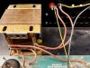
Some mechanical hum from power transformer, but when pressed it´s quiet enough, so a couple of rubber grommets should do the trick.
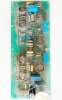
Some pic of the PCB for you gadget73, if you can spot the type of construction.
Some mechanical hum from power transformer, but when pressed it´s quiet enough, so a couple of rubber grommets should do the trick.
Some pic of the PCB for you gadget73, if you can spot the type of construction.
Attachments

Subchannel
Active Member

toasty construction is what that is 
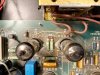
looks like pin 2 (grid) ties to a common point via those resistors on each, so that jives with how I suspect its wired.
Can't tell what pin 3 (cathode) goes to, but I'd expect a common resistor but I suppose you could do individual resistors or it might be grounded if this runs fixed bias. Expect about a 250-300 ohm resistor if its got one per-tube, or about 125-150 ohms per pair. Common for all 4 would be in the 70 ohm range. I'm guessing fixed bias though based on the wee little bridge rectifier in the back corner. Would need to make maybe 20 volts at piddly amounts of current.
Pin 7 is the plate, and those are jumped topside so input and output is parallel on each side, so definitely push-pull-parallel
I can see why they made it this way, its an easy way of adapting an existing 2 channel stereo board into a 1 channel double power amp, but its not the most efficient way in terms of parts or current use. If I were doing it, I'd have just used a single phase inverter tube and maybe paralleled the two triodes in the voltage amp stage. Could still make that work with the existing board, it would involve a couple more bodge wires but it would eliminate one tube from the mix without actually changing the way the amp functions or forcing a re-design of the circuit board. Whether it would actually perform better, don't know.
looks like pin 2 (grid) ties to a common point via those resistors on each, so that jives with how I suspect its wired.
Can't tell what pin 3 (cathode) goes to, but I'd expect a common resistor but I suppose you could do individual resistors or it might be grounded if this runs fixed bias. Expect about a 250-300 ohm resistor if its got one per-tube, or about 125-150 ohms per pair. Common for all 4 would be in the 70 ohm range. I'm guessing fixed bias though based on the wee little bridge rectifier in the back corner. Would need to make maybe 20 volts at piddly amounts of current.
Pin 7 is the plate, and those are jumped topside so input and output is parallel on each side, so definitely push-pull-parallel
I can see why they made it this way, its an easy way of adapting an existing 2 channel stereo board into a 1 channel double power amp, but its not the most efficient way in terms of parts or current use. If I were doing it, I'd have just used a single phase inverter tube and maybe paralleled the two triodes in the voltage amp stage. Could still make that work with the existing board, it would involve a couple more bodge wires but it would eliminate one tube from the mix without actually changing the way the amp functions or forcing a re-design of the circuit board. Whether it would actually perform better, don't know.
Subchannel
Active Member
Soldered up som new wires on the other amp, it´s also working! I think this was a kit, it´s the worst soldering job I´ve ever seen (and I´ve seen a lot).
Thanks for very good info gadget73, most apreciated. Do you know why he chose ECC88 for input buffer? From what I´ve read this is a HF tube?
Next up is the preamp, but after summer vacation. Then total restoration, new paint on the enclosure, new fronts, new caps.
Thanks for all the good input!
Thanks for very good info gadget73, most apreciated. Do you know why he chose ECC88 for input buffer? From what I´ve read this is a HF tube?
Next up is the preamp, but after summer vacation. Then total restoration, new paint on the enclosure, new fronts, new caps.
Thanks for all the good input!
The ECC88 / 6DJ8 / 6922 became the hot ticket for audio stuff sometime in the early 80s it seems. I don't know exactly why honestly. They were intended as RF amps, oscillators, and mixers in tuners but somewhere along the line somebody decided it was the thing to use for audio circuits. My 80s tube hybrid preamp uses them, the only other thing I believe I own with that tube is an FM tuner.
possibly gets into one of those things where the answer is "it sounds good" even though on paper it might not actually have anything to suggest why its better or worse than something else. Thats the good and bad thing about tubes, every tube of a given type is identical on paper but different brands and constructions often sound different when you plug them in.
possibly gets into one of those things where the answer is "it sounds good" even though on paper it might not actually have anything to suggest why its better or worse than something else. Thats the good and bad thing about tubes, every tube of a given type is identical on paper but different brands and constructions often sound different when you plug them in.

Pio1980
AK Member
Tektronix used them in the o'scopes.The ECC88 / 6DJ8 / 6922 became the hot ticket for audio stuff sometime in the early 80s it seems. I don't know exactly why honestly. They were intended as RF amps, oscillators, and mixers in tuners but somewhere along the line somebody decided it was the thing to use for audio circuits. My 80s tube hybrid preamp uses them, the only other thing I believe I own with that tube is an FM tuner.
possibly gets into one of those things where the answer is "it sounds good" even though on paper it might not actually have anything to suggest why its better or worse than something else. Thats the good and bad thing about tubes, every tube of a given type is identical on paper but different brands and constructions often sound different when you plug them in.
Subchannel
Active Member
This took a WHILE, to say a least. The two Edison 24 amp´s have been resting on my shelf since last mail. Decided to finish them, but after recap/ rewiring/ cleaning, one amp is distorting heavily when playing anything over low/ mid volume (the preamp is still in parts, so not connected here). Tried the other amp, not restored but fixed, same tubes, and this does not distort. This is not the typical tube overdrive, more like a transistor fuzz pedal/ crackling distortion.I´ve gone through every solder point, and both amps are wired identically.
Replaced on one amp:
-new rectifier bridge
-new electrolytics (same value)
-new film caps (2 0.47uF and 2 0.1uF. Was Ero, replaced with Clarity Cap)
-new 33ohm/ 5w resistor in PSU
-new speaker and rca connectors
-new speaker and signal wires.
As for the two black wires from the PSU caps, these where put underneath the PCB on the restored amp.
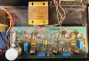
2 pics of restored amp, 2 pics of non restored.
Any thoughts?
Thanks in advance!
Replaced on one amp:
-new rectifier bridge
-new electrolytics (same value)
-new film caps (2 0.47uF and 2 0.1uF. Was Ero, replaced with Clarity Cap)
-new 33ohm/ 5w resistor in PSU
-new speaker and rca connectors
-new speaker and signal wires.
As for the two black wires from the PSU caps, these where put underneath the PCB on the restored amp.
2 pics of restored amp, 2 pics of non restored.
Any thoughts?
Thanks in advance!
Attachments

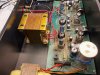
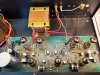

What was the status before you started replacing things ?This took a WHILE, to say a least. The two Edison 24 amp´s have been resting on my shelf since last mail. Decided to finish them, but after recap/ rewiring/ cleaning, one amp is distorting heavily when playing anything over low/ mid volume (the preamp is still in parts, so not connected here). Tried the other amp, not restored but fixed, same tubes, and this does not distort. This is not the typical tube overdrive, more like a transistor fuzz pedal/ crackling distortion.I´ve gone through every solder point, and both amps are wired identically.
Replaced on one amp:
-new rectifier bridge
-new electrolytics (same value)
-new film caps (2 0.47uF and 2 0.1uF. Was Ero, replaced with Clarity Cap)
-new 33ohm/ 5w resistor in PSU
-new speaker and rca connectors
-new speaker and signal wires.
As for the two black wires from the PSU caps, these where put underneath the PCB on the restored amp.
2 pics of restored amp, 2 pics of non restored.
Any thoughts?
Thanks in advance!
Subchannel
Active Member
Thanks for the input.
When I got them I connected everything and turned them on via Variac. Then testet both on my 15" Tannoy´s, as I recall both played good.
I have not measured yet, but double checked every new cap and solder point.
Although far from an expert, I have repaired and soldered a LOT over the years, but the problem could of course be that something is done wrong.
The fault can resemble a diode distortion, a thin very sharp dist.
When I got them I connected everything and turned them on via Variac. Then testet both on my 15" Tannoy´s, as I recall both played good.
I have not measured yet, but double checked every new cap and solder point.
Although far from an expert, I have repaired and soldered a LOT over the years, but the problem could of course be that something is done wrong.
The fault can resemble a diode distortion, a thin very sharp dist.
Subchannel
Active Member
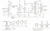
Have now measured almost every component and solder joint. There´s some small variations here and there. On low voltage it varies a few hundred mV, on high voltage difference can be up to 7-9VDC. This is a non regulated PSU, so that should be within specs i guess?
The only big difference I´ve measured is:
R34: the working amp measures 0VDC, the faulty one measures 7.95V.
R7: working amp measures 7.95V, faulty one measures 11.92V
And that´s kind of strange since this is two identical amps coupled into one PPP, so both r34 and R7 should be almost identical? And why 0V on R34 on working amp?
Schematics is of Edison 12. Edison 24 is the same only two 12.
The only big difference I´ve measured is:
R34: the working amp measures 0VDC, the faulty one measures 7.95V.
R7: working amp measures 7.95V, faulty one measures 11.92V
And that´s kind of strange since this is two identical amps coupled into one PPP, so both r34 and R7 should be almost identical? And why 0V on R34 on working amp?
Schematics is of Edison 12. Edison 24 is the same only two 12.
Attachments
Subchannel
Active Member
That´s R34/ R7.
ok, if you're getting no voltage drop across one, you have no current flow in that tube or tubes. Not sure if its one per tube or one per pair. If you know the tubes aren't bad, confirm it has plate and screen voltage. Either will cause no current flow, but if its got screen but no plate supply, often that will kill the tubes. The screen will attempt to be an anode and they just do not survive that kind of abuse.
Subchannel
Active Member
Thanks Gadget73, but the strange thing is that there´s zero volt over R34 on the working amp?? Have measured both sides of PCB to be shure. Also measured resistance, 150ohm.
One for each pair.
One for each pair.