• Please note that Audiokarma will be offline briefly for updates early on Monday morning, September 28th.

EH SCOTT 510 Console tube amps to be modded as mono blocks.

kve777

AK Subscriber
Subscriber
Below is the schematic for the EH Scott 510 console. I have two amps, one tuner and two of the Jensen Coaxials.

1. I'm not going to use the tuner, so looking at the schematic and it appears I can eliminate the 25Z6 voltage doubler. Anyone disagree?

2. It looks like I should put another 6SN7 in the 25Z6 socket and wire it as seen as the 2nd AF Amp/Cathode Follower in the tuner section, basically from just before the 100kΩ resistor (Above C5) as my input jack location. I can't read the R#. Dose that sound right?

Any other suggestions? I'm not interested in an input attenuator. I am interested in using the choke and possibly a better biasing arrangement.
EH_Scott_510_schem.gif
 
Register to hide this ad
25Z6 looks to be used as a standard full wave rectifier, but its only feeding the tuner. Looks like you can ditch it, C2, and L1. Depending on voltage output though, you might consider making it the screen supply. It should be more solid than the stock design dropping through resistors. That should give slightly more power output and might reduce distortion a smidge if the screen supply doesn't sag under load. They draw a lot of current on a 6L6, though total drop resistance on that circuit isn't overly huge. Just a thought.

Depending on current capacity of the choke, maybe it could replace the first 375 ohm resistor in the power supply.

If you ditch it, the 25vac winding that feeds the heater on it can become a fixed bias supply winding to replace the cathode bias rig it currently uses. Short of that though, I'd probably leave it alone.

You'd need the last 6SN7 on the tuner chassis to complete the feedback loop. Copy that stage on the amp if you ditch the 25Z6 and it should make for a complete amp. Keep the 100K grid resistor (R40 ?) and make that your input. Stick a cap between that point and the input jack if you want some DC blocking. 0.1-0.22uf would do fine. This would make for a fairly low input impedance tube amp. You can bump that grid resistor probably as high as 470K if thats a problem for your preamp.
 
Is EH Scott stuff up to hifi specs? I know these were very expensive when new but not sure how wide-band they are.
 
25Z6 looks to be used as a standard full wave rectifier, but its only feeding the tuner. Looks like you can ditch it, C2, and L1. Depending on voltage output though, you might consider making it the screen supply. It should be more solid than the stock design dropping through resistors. That should give slightly more power output and might reduce distortion a smidge if the screen supply doesn't sag under load. They draw a lot of current on a 6L6, though total drop resistance on that circuit isn't overly huge. Just a thought.

Depending on current capacity of the choke, maybe it could replace the first 375 ohm resistor in the power supply.

If you ditch it, the 25vac winding that feeds the heater on it can become a fixed bias supply winding to replace the cathode bias rig it currently uses. Short of that though, I'd probably leave it alone.

You'd need the last 6SN7 on the tuner chassis to complete the feedback loop. Copy that stage on the amp if you ditch the 25Z6 and it should make for a complete amp. Keep the 100K grid resistor (R40 ?) and make that your input. Stick a cap between that point and the input jack if you want some DC blocking. 0.1-0.22uf would do fine. This would make for a fairly low input impedance tube amp. You can bump that grid resistor probably as high as 470K if thats a problem for your preamp.
Thanks, I feel like I'm on the right track!
 
Is EH Scott stuff up to hifi specs? I know these were very expensive when new but not sure how wide-band they are.
I guess I'll find out! My hearing isn't exactly up to Hifi Specs, either, LOL.
Seriously, they just might be pretty good, it's a simple design. I could scrap the circuitry and do something more modern, just use the iron. Those trannies are rather large, so I'm hopeful.
 
EH Scott stuff was pretty hifi in it's day. Exactly how good it is you'd have to measure but I bet it doesn't suck. My 800B with it's Jensen coax sounds pretty nice. I've never measured it though. Don't think its a feedback amp either, the 510 probably performs better than my 800B does.
 
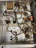
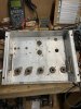
...on my way. Both chassis were stripped, polishing attempted, but sadly the pitting was too deep. Bright aluminum paint over self etching primer. Black enamel for the transformers. Re-population has begun!
 
B097142D-D3E8-40F9-AEB6-E0A9A7B41027.jpeg DB955543-51D4-4A2E-8220-C86B6593589F.jpeg F47C7A99-2A17-4663-B58B-DFC62F0FD0A0.jpeg
 

Attachments

  • 6540357F-2F4C-48DE-92FC-C63D1AA33737.jpeg
    6540357F-2F4C-48DE-92FC-C63D1AA33737.jpeg
    166.3 KB · Views: 66
Last edited:
Very nice progress ! You picked nice prototyping chassis ! What happened to the 510 schematic up top ?
 
No prototype. That’s the original chassis. Schematic was posted a while ago. They are on the web. I ordered a bunch of 600 volt cloth covered wire for a really cool looking build.
 
I knew that...You are prototyping with the nicely refinished chassis. If you remove that "extra rectifier" you have an extra socket for gain/drive. If you choose, you can always use ss rectifiers underneath, in order to use the extra, lower HV taps to power the front end tubes....Enjoy your building !...
 
That's the plan, two 6SN7's in the front, 2 6L6's in P-P. I plan on keeping the tube rectifier, possibly going to 5AR4. Sadly one of the chokes is open. I wanted to put them in the HV. I might put both OPT's with one PT on another chassis for a stereo unit. 5AR4 rectifier should allow that. Thoughts?

How about adding negative feedback? Zobel network?
 
Feedback is good, pentodes have high output impedance and don't work that well without it. This has feedback in stock form, if you chase the connection from the output trafo through the umbilical you'll see where it feeds out to the speaker and to the cathode of V9 through a couple of resistors. Honestly the easy thing to do here is use the entire amp circuit from V9 through the output tubes, but relocated to the main amp chassis. That would be a pair of 6SN7 per-channel.

If you can do dual 5AR4's for stereo it would be better but I'd probably consider leaving it as two mono amps. Zero chance of power supply crosstalk and the supply will be more than sufficient to handle the ~25w this will likely make even with a single rectifier.
 
So, I finished #1 and it works. Sounds pretty good, too. But the gain seems low. Going to have to add a first stage amp section. Original design uses a 6SQ7. Kind of a half a 12AX7-ish tube with two diodes. High MU at amplification factor of 100. I'm thinking of using Russian 6N2P-EB with the triodes in parallel. I could put a gain pot right after it, before the second stage 6SN7. I could also go with 6SQ7, 6SF5, 6AV6, 12AX7 or even 6DJ8 if I wanted. Any thoughts or suggestions?
 
Back
Top Bottom