• The move to the new server is done. There are some software and database maintenance updates in process. This has us passing the hat around to help out. We appreciate any donations. Seriously, even a dollar helps. The payment page may be found here - https://www.audiokarma.org/support.html

EICO HF-89 Power Supply Modifications?

mrk229

AK Subscriber
Subscriber
Greetings.
As noted in many places the EICO power supplies were mostly built to a just adequate specification.
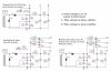
I am currently rebuilding an HF-89 and want to upgrade the power supply. Looking at various threads here at AK and other places has given me some ideas and they are presented in the image file attached.

"A" is the original circuit with uprated capacitor values
Clipboard02.jpg

My question for the tube gurus here (that does not include me by any stretch. "Tube Noob")

Will the "C" variation create a much cleaner supply for the phase splitter and input circuits?

Or would a variation of the "B" circuit that places a smaller choke before or after R46 be a better solution? I show the choke/resistor combo detached in the "B" block

The dual choke "C" circuit saves me buying and finding space for a third choke in the "B" variation.

The chassis does not have room for a single larger choke, top or bottom. I can fit two Triad C-24X chokes underneath without a lot of trouble.

The C-24X is rated at 240mA and a single one would be pushing the limits just at idle.

So what do you think?

Thanks in advance for your advice.

Matt
 
Last edited:
Register to hide this ad
I would opt for a solution not drawn. Parallel the chokes for double the current at half the inductance. The Z tap comes after the chokes and services both channels. Reverse the positions of the 130 uF and 470 uF caps but make sure the 470 uF cap can withstand the full unloaded plate voltage.

Use cascaded R-C filtering after the Z tap for each of the Y and X taps which also service both channels.
 
I'm currently modifying two HF-89s with this circuit.


View attachment 2471153

That was the basis of the "B" circuit with a few minor value changes based on parts I already had.

I was wondering if moving the X and Y voltage feed point to a post choke position ("C" diagram) would noticeably clean up the power to the front end?
 
I would opt for a solution not drawn. Parallel the chokes for double the current at half the inductance. The Z tap comes after the chokes and services both channels. Reverse the positions of the 130 uF and 470 uF caps but make sure the 470 uF cap can withstand the full unloaded plate voltage.

Use cascaded R-C filtering after the Z tap for each of the Y and X taps which also service both channels.


Can you explain your reasoning to help me understand what this would accomplish?

Would the much lower capacitor values in the voltage doubler be an issue? The stock values were 300uF (see diagram)

I have posted an edited version of the diagram with changes as you suggested.

cb89.jpg
 
That 3k resistor between the caps should provide plenty enough filtering. I don't really see that adding a choke into the mix for the front end would clean it up enough more to bother with. One advantage of not including the choke, you won't get the voltage swings developed across the choke influencing the supply to the front end quite so much.
 
That 3k resistor between the caps should provide plenty enough filtering. I don't really see that adding a choke into the mix for the front end would clean it up enough more to bother with. One advantage of not including the choke, you won't get the voltage swings developed across the choke influencing the supply to the front end quite so much.

Thank you for the response. The diagram that BuzzK posted was my jumping off point. Seems I may not need to jump any further :).
 
I was wondering if moving the X and Y voltage feed point to a post choke position ("C" diagram) would noticeably clean up the power to the front end?

IMO the loss of isolation from the outputs would be a downside of doing it that way. Instead, I'd install a small coil in series with the 3K resistor (and adjust the values accordingly).

I am able to fit the two chokes and the EFB™ circuit under the chassis. There is room for a small Hammond choke if you want one. But as gadget73 pointed out, the 3K will probably suffice.
 
I don’t think you will notice any difference in noise reduction between your B and C versions. The phase inverter being a form of differential amplifier will reject nearly all of the common mode noise from the PS at that tap point, and the X tap has two stages of R/C filtering in front of it already.

Do consider swapping your capacitor bank sizes as I mentioned above though. I think you will get a little less transient ring, plus you’ll have more low impedance energy storage on tap and available right at the output stage where you really need it, but at the expense of slightly higher ripple. I haven’t modeled this in the simulator so this is my belief from past experience.
 
IMO the loss of isolation from the outputs would be a downside of doing it that way. Instead, I'd install a small coil in series with the 3K resistor (and adjust the values accordingly).

I am able to fit the two chokes and the EFB™ circuit under the chassis. There is room for a small Hammond choke if you want one. But as gadget73 pointed out, the 3K will probably suffice.

I plan on adding the EFB™ circuit as well.
 
The original circuit didn’t use a choke so in that case you can put the larger caps on the doubler. Adding a choke creates a tank circuit which can introduce transient ringing. You can address that by making the downstream cap about 2x larger than the upstream cap
 
Back
Top Bottom