

You are using an out of date browser. It may not display this or other websites correctly.
You should upgrade or use an alternative browser.
You should upgrade or use an alternative browser.
Eico ST-40, Redo/Modo
- Thread starter Kegger
- Start date

Dandy
Addicted Member
Thanks Kegger.
Here are my measurements with proper 6L6GCs.
Power supply: 394V at the GZ34, 370V at U to output centre taps (should be 355) and 343V at test point (should be 320). These are all about 4-6V lower than with the 5881s.
Plates of the 12AT7: 108/109V (pin 6, should be 96) but 182V (pin 1, should 195). I kept the 82k resistors there. Cathodes of 12AT7: 1.05V at pin 8 (should be 1V) and 109V (should be 97.5V). These are about the same or a bit lower than with the 5881s.
Plates of 6L6s: around 359V (should be 352). Lower than withthe 5881s by about 3V.
As the voltages are lower with 6L6s, maybe I'll just leave these in. (I got them with a nice batch of used guitar tubes some years ago.)
Here are my measurements with proper 6L6GCs.
Power supply: 394V at the GZ34, 370V at U to output centre taps (should be 355) and 343V at test point (should be 320). These are all about 4-6V lower than with the 5881s.
Plates of the 12AT7: 108/109V (pin 6, should be 96) but 182V (pin 1, should 195). I kept the 82k resistors there. Cathodes of 12AT7: 1.05V at pin 8 (should be 1V) and 109V (should be 97.5V). These are about the same or a bit lower than with the 5881s.
Plates of 6L6s: around 359V (should be 352). Lower than withthe 5881s by about 3V.
As the voltages are lower with 6L6s, maybe I'll just leave these in. (I got them with a nice batch of used guitar tubes some years ago.)
Last edited:

I'll Double check your voltages, but using "6L6GC" output tubes at those voltages
you should be fine, might be pushing non GC variants but I'll look when I get to it.
Congrats!
I've run old metal-can 6L6s on 380v no problem. They're tough buggers.

As long as it's not over 400v, it's fine for pretty much any 6L6, IME. Just keep the plate current at an appropriate level- anything under 45ma per tube, at 377v, should be fine. My Magnavox AMP150 6L6 conversions tend to be right about at this spec... makes for a solid 25w/ch or so.
Regards,
Gordon.
Dandy
Addicted Member
Thanks for checking this Gordon and Kegger.
For R70, 72 etc I put in new 1.2k resistors to the 6L6 grids, and replaced the 83k resistors in the splitter with 56k as recommended. It doesn't seem to have affected the voltages much, but it sounds great: clean and very silent.
I have to admit I don't usually measure plate current, so I don't know how to to do it right, without placing the meter across the actual current. It seems easier to measure cathode current at idle with a 10ohm (or 1 ohm) resistor from cathode to ground. Is this okay?
For R70, 72 etc I put in new 1.2k resistors to the 6L6 grids, and replaced the 83k resistors in the splitter with 56k as recommended. It doesn't seem to have affected the voltages much, but it sounds great: clean and very silent.
I have to admit I don't usually measure plate current, so I don't know how to to do it right, without placing the meter across the actual current. It seems easier to measure cathode current at idle with a 10ohm (or 1 ohm) resistor from cathode to ground. Is this okay?

Kegger
R.I.P. 1/12/1966 - 6/1/2017
Going by my original design.
It's 250ohm cathode resistor shared by 2 tubes.
And 25.5v marked at the cathode, so divide that by 250
an you get roughly 100ma (.102) per pair or 50ma a tube.
That is how you would figure plate/screen current, subtract
say 4ma for the screen and yur 46ma plate current per tube.
So measure the cathode voltage on the output tubes an divide
that by the cathode resistor used to figure plate/screen current.
It's 250ohm cathode resistor shared by 2 tubes.
And 25.5v marked at the cathode, so divide that by 250
an you get roughly 100ma (.102) per pair or 50ma a tube.
That is how you would figure plate/screen current, subtract
say 4ma for the screen and yur 46ma plate current per tube.
So measure the cathode voltage on the output tubes an divide
that by the cathode resistor used to figure plate/screen current.
Last edited:
Kegger
R.I.P. 1/12/1966 - 6/1/2017
Thanks again. Wish I was a faster learner
Just takes repeated effort, do that and you'll be just fine. :yes:
Dandy
Addicted Member
My voltages are 29V for one pair of tubes and 27.6V for the other, i.e. 57mA per tube for one pair and 53mA for each of the other pair. Do I raise the value of the cathode resistors to lower this?
A further thought, I wonder if a different rectifier would lower the B+ beneficially for the whole circuit? 5V4, or even 5Y3?
A further thought, I wonder if a different rectifier would lower the B+ beneficially for the whole circuit? 5V4, or even 5Y3?
Last edited:
Dandy
Addicted Member
I tried a 5V4 for size. It seemed to work okay, but didn't drop the voltage at the cathodes much.
Will do the math first thing in the morning. I need to read up a bit to understand what plate dissipation is, and so what % to aim at. I see Aikenamps talk about 70% as a maximum when the amp is idling.
Will do the math first thing in the morning.
I need to read up a bit to understand what plate dissipation is, and so what % to aim at. I see Aikenamps talk about 70% as a maximum when the amp is idling.
Kegger
R.I.P. 1/12/1966 - 6/1/2017
6L6GC has plate wattage rating of 30.
Say shooting for 80% of that and 24W of dissipation or less would be just fine.
Standard 6L6 has 19w plate so 80% of that an 15W of dissipation or less is fine.
--
And I gave the simple math in this thread to figure plate dissipation per tube here.
.
Say shooting for 80% of that and 24W of dissipation or less would be just fine.
Standard 6L6 has 19w plate so 80% of that an 15W of dissipation or less is fine.
--
And I gave the simple math in this thread to figure plate dissipation per tube here.
.
Last edited:
Dandy
Addicted Member
Thanks again! I waited till the morning as I got your message too late last night to work safely. I've done the math with the 5AR4 and 6L6GCs back in place. The measurements were done with the amp warmed and idling.
Cathode voltages are 27 or 28V, say 27.5V. Divided by shared cathode resistor of 250R = 110mA, or 55mA per tube. Less 4mA for screen = 51mA per tube.
Plate to cathode voltage is 328V. Multiplied by 0.051A = 16.7W 16.7 divided by 30 = 0.56, or 56%.
*If* I've done this right, it looks very safely in the ballpark for 6L6Gcs.
Cathode voltages are 27 or 28V, say 27.5V. Divided by shared cathode resistor of 250R = 110mA, or 55mA per tube. Less 4mA for screen = 51mA per tube.
Plate to cathode voltage is 328V. Multiplied by 0.051A = 16.7W 16.7 divided by 30 = 0.56, or 56%.
*If* I've done this right, it looks very safely in the ballpark for 6L6Gcs.
Dandy
Addicted Member
Whew. Thanks to your patient teaching, I can see that it is quite easy if you know what to measure.
Now I'll spring for 8 of those nice Russian PIO caps.
p.s. 24 hours of listening later, I am amazed at the improvement this redo has made to this amp. I like this first taste of the sound of triode with no feedback.
Now I'll spring for 8 of those nice Russian PIO caps.
p.s. 24 hours of listening later, I am amazed at the improvement this redo has made to this amp. I like this first taste of the sound of triode with no feedback.
Last edited:
Listener13
Active Member
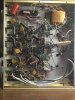
I just finished the Kegger ST-40 Super Mod and I must say the amp sounds awesome to my old ears. I hooked it up with some Cerwin Vega D-5 speakers and it rocks out. Like Dandy, the cathode voltage is off from side to side and high, the 100 ohm pot does nothing. I have 28.9vdc and 27.8vdc feeding back on top of the 6.3vac. I rewired some of the amp because the builder used the wrong size wire stripper and wires were popping/breaking off all over. I had some Russian k40y-9 PIO 400v caps, had to wrap a couple because they are kind of large. Also used Sovtek 6L6WXT+ tubes. Now all I need are some better matched 12at7 tubes
Hey, It's not a perfect world and sometimes a blind squirrel finds an acorn.

Hey, It's not a perfect world and sometimes a blind squirrel finds an acorn.
Last edited:

Listener13
Active Member
Please tell us all more Dandy, or at least me, lol. The loudness mod was done. It sounds great and very detailed now with no hum, all the capacitors were replaced except the disks. I have not tried the phono, AM/AM/FM or tape stages yet, just the AUX/MPX.
I have another in the heap that needs a few knobs and other than that, it is complete.
I have another in the heap that needs a few knobs and other than that, it is complete.