• The move to the new server is done. There are some software and database maintenance updates in process. This has us passing the hat around to help out. We appreciate any donations. Seriously, even a dollar helps. The payment page may be found here - https://www.audiokarma.org/support.html

Emory Cook and Gus Jose's "The Ultimate Amplifier" (Long Post Warning)

AlexHempel

AK Subscriber
Subscriber
I've always loved mono tube amps with big transformers, and I also enjoy browsing the auction site (these are both undesirable traits). In any case, I make a mental note of every large, interesting pre-1960 mono amp that pops up. A while ago (I think a year or so?) I saw an amplifier called the "Cook-Langevin Ultimate Amplifier" listed for a hefty sum. It used a quad of 6550s and had massive iron. Clearly professionally-built based on the silk-screening and the impeccable wiring, but I could find absolutely no documentation nor was there any other evidence of this amplifier's existence whatsoever. Moreover, the transformers did not have typical Langevin potting. I ended up letting the amplifier go because I knew I would never find a second (nor the parts for a second) and I generally want stereo pairs.

Some time later, I saw another amplifier listed as the "Cook Langevin Ultimate Amplifier." This one, however, used identifiable Langevin iron -- the 316A output transformer, normally found on a Langevin 101-3101 quad 6L6 PA amplifier. Best of all, the seller was including a spare Langevin 316A OPT and a 100A PT. This was essential for having a second amplifier, as the output transformer is unobtanium. I had no idea what to make of the relationship between this listing and the first one, seeing as the transformers, tube complement, and chassis seemed completely different. However, I decided this would make an excellent project.

Following a six-month delay (waited until after a move), the amplifier arrived today, along with the spare iron and a big folder containing documentation. There is an article, which I will upload in the next post, which describes the amplifier and the design philosophy behind it. Apparently, the Langevin iron was the only off-the-shelf transformer which met the spec. This article confirms that the "Cook" in question was Emory Cook, an early stereo pioneer. Lastly, scrawled notes in the folder indicate that Cook later decided to sell a version of this amplifier using different Langevin iron, 6550s, and no 0D3 gas regulators; this must have been the first amplifier I found on Ebay.

Anyways, my goal is to upload all the documentation for posterity and to build a second amplifier using the iron. As far as I am aware, the schematic was not previously available online -- some DIYAudio user posted the article's first page a while ago, but not the entirety. In addition to these magazine copies, the folder contains what appear to be original spec sheets for various Langevin parts and an original factory wiring diagram for the Langevin 101-3101. There are also dozens of pages of printed email threads and Ebay message exchanges. I think I will reserve speculation regarding whose amplifier this was for a future post (if anyone even cares).

And, of course, pics of the amplifier are attached here (soda can for scale). I have not yet gotten around to cleaning it, nor have I plugged in the tubes (most of which are Tung Sol originals).
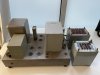
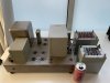
image2 (3).jpeg

image3 (1).jpeg

image0 (9).jpeg
 
Last edited:
Register to hide this ad
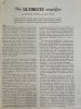
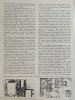
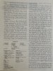
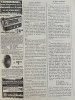
Attached to this post are pictures of the article and the subsequent response editorial:
 

Attachments

  • image1 (4).jpeg
    image1 (4).jpeg
    210.8 KB · Views: 37
  • image2 (4).jpeg
    image2 (4).jpeg
    233 KB · Views: 36
  • image3 (2).jpeg
    image3 (2).jpeg
    212.7 KB · Views: 36
  • image0 (10).jpeg
    image0 (10).jpeg
    251 KB · Views: 36
  • image1 (5).jpeg
    image1 (5).jpeg
    259.3 KB · Views: 41
Realized while looking at the schematic that the Langevin PT supplied as a spare isn't even close to being the right transformer. The design calls for 1100VCT and the Langevin PT is 860VCT. By some miracle, Surplus Sales of Nebraska (great source for big iron) has stock of the transformer originally specified: a Chicago P(X)R-300. Just ordered one, now I guess I have a spare Langevin PT.
 
Last edited:
Yes, it's High Fidelity volume 4 issue 10. In fact, someone else beat me to the punch: the entire issue is digitized at: https://worldradiohistory.com/Archive-All-Audio/Archive-High-Fidelity/50s/High-Fidelity-1954-Dec.pdf. I was not aware of this until I made a post on a DIYAudio thread and somebody linked this.

Wow they have everything cataloged at that website
https://worldradiohistory.com/Archive-All-Audio/

Amazing what you can find on the internet, including the transformer from the 50's you just happen to need. Going to be a pretty awesome set when finished. Just the mono amp alone is very cool.
 
Ok, so apparently Nebraska Surplus' website doesn't update frequently and the PSR-300 is actually not in stock. Now I need to source another 550-0-550 transformer. I'd rather have something vintage and potted, or else it'll stick out like a sore thumb. The closest transformer I see on Ebay now is 550-0-550 at 500ma, which is a higher current rating than the original at 300ma. I'm guessing this will give me high B+. Anyone have a sense of how big of a problem this will be and whether a dropping resistor is sufficient to fix it? I've also ordered a different choke than the original, so I'm guessing the power supply on the second unit will require some tweaking before the voltages are good.

Also, I've realized my amplifier contains some modifications. I aim to post an updated schematic with the actual connections in my amplifier. Then I have to decide which of these I want to incorporate into the second. For instance, this amplifier has 10 ohm resistors in series with the shared 90 ohm cathode bias resistor; guess a tech was messing with the bias.
 
Last edited:
I was under the impression that power transformers give the specified secondary voltage at the specified load, i.e. at 550v when loaded to 500ma and higher than 550v with less load. Am I misunderstanding and the voltage specified is typically un-loaded? For instance, Hammond's transformers have an un-loaded voltage acceptance criteria which is noticeably higher than the rated load voltage (910v vs. 850v for this example: https://www.hammfg.com/files/parts/pdf/279X.pdf.)
 
Last edited:
They do, but it won't be as significant a difference as no load to full load. If you have to add a smidge of resistance thats easy enough to do, but I suspect it won't be a massive change. Could model it in PSUD2 if you can measure the DC resistance and unloaded voltages of the windings on each. Just stick some fixed value load in there, say maybe 250ma for reference purposes and see what it looks like.
 
Hunt around for a wee bit; those Chicago power Iron come up from time to time. Hopefully not when somebody else absolutely has to have just that one at the same time...LOL For the OE, potted stuff, it won't exactly be inexpensive. Might be best to get a new pair wound( Heyboer for example ). I don't have good numbers on just how much of an audible effect two different power TX's would have, and so just follow my aesthetic/general paranoia and do what ever is needed to run pairs.
cheers,
Douglas
 
My mentor gave me a procedure for determining the current rating of a transformer.

Unload the secondary and measure the open voltage. Then load the secondary until that figure drops by 10% then use an amp clamp to measure the current. That's he "conventional" method.
Work it backwards
Your replacement transformer makes 500 miliamps at 1100 v primary (be very careful)
Our formula, worked in reverse suggests the new one will make probably 1200 volts unloaded, but you're not running unloaded.

Long story longer.
500 miliamps is ideal.
Going up in current rating is a good thing, you'll never approach the overload point under normal use. It will probably run cooler and quieter as a result.
 
My mentor gave me a procedure for determining the current rating of a transformer.

Unload the secondary and measure the open voltage. Then load the secondary until that figure drops by 10% then use an amp clamp to measure the current. That's he "conventional" method.
Work it backwards
Your replacement transformer makes 500 miliamps at 1100 v primary (be very careful)
Our formula, worked in reverse suggests the new one will make probably 1200 volts unloaded, but you're not running unloaded.

Long story longer.
500 miliamps is ideal.
Going up in current rating is a good thing, you'll never approach the overload point under normal use. It will probably run cooler and quieter as a result.

Thank you, this is very helpful. Luckily, @dcgillespie actually found a PSR-300 for me, so I'll be using that. Goal for this weekend is to fire up the amplifier and give it a listen.

On another note, I have some questions for the gurus. In a few places, the schematic explicitly calls for parallel resistors rather than a single resistor, and it's probably not done for power dissipation because in one case the parallel resistors are only 1/4 watt. Curious if anyone knows why this would be necessary.

Another thing -- the article explains the use of two mica caps by saying "A strange thing about three-stage feedback -- one of the three stages must be a lot "worse" than the other two in order to keep the whole circuit stable, so we have put two .0015uf mica condensers at the output of the first stage in order to wreck it purposefully." The mica caps connect the plates of the 12AX7 triodes to ground before the coupling cap -- also something I've never seen and don't understand. Is this a low-pass filter and, if so, where is the resistor/inductor component?

Obviously, I'd rather avoid these weird component selections if possible. But, given that my assembled amp has both the mica caps and the parallel resistors, I can't rule out their necessity.
 
Just a uswag, a 4 stage cap coupled driver provides ample opportunities for phase shift and instability in a global FB amp. It needs the stuff to not go unstable.
 
Alex -- A couple of answers to your questions:

1. The paralleled resistors that are clearly not addressing a dissipation issue, were done no doubt to zero in on a more accurate value than the nearest standard production value could provide. This certainly speaks to a high level of adjustment of the amplifier.

2. The mica caps you are referring to in fact help to form a low pass filter, in more modern times called a "step network". Left unchecked, NFB would attempt to produce a HF response that goes to the moon. Around one or two stages, there's only so much practical NFB that can be applied, so this tendency is basically kept in check. But placed around 3 or more stages, then there's enough gain for a NFB amplifier to really get into trouble. A step network is the most common way to not so much "wreck" the response of one stage, but introduce a controlling element so the amplifier can't "take off" in an effort to reach the moon with regards to its HF response characteristic. There are similar controlling elements (hi pass filters) installed to prevent the same thing from happening at the low end of the spectrum as well.

3. As for your question "where is the resistor/inductive component?" regarding the low pass filter? It's well hidden and not shown on the schematic, but is actually the plate resistance of the tube itself -- of which the 12AX7 has copious amounts of. There are other designs that install step networks in this fashion -- Mac is one of the first that comes to mind.......

HF step networks are best tuned using 10 kHz square waves as a test signal, operating at (typically) a 1 watt output level. LF networks are best tested with pulse signals, with a digital storage scope really coming in handy for that work.

I hope this helps!

Dave
 
I know that article was written in an "irreverent" style (a.k.a. "refreshing manner") for a 1950's technical journal, but I sure don't like the choice of words used in this paragraph below because it provides no basis for understanding of the concepts presented. Why didn't the magazine editor catch these I wonder?

To quote:

"Now, on to the Never-Never Land salt mines, to battle with dragon resistors and condensers. A strange thing about three-stage feedback -- one of the stages must be a lot "worse" than the other two in order to keep the whole circuit stable, so we have put two .0015-mfd mica condensers at the output of the first stage in order to wreck it purposefully. The remaining two stages (including the output transformer) have to be so good that just the matter of the 1.0-mfd blocking condensers can upset them."

I've underlined the phrases above I'm struggling with
  • "Never-Never Land salt mines" - I think this means the work he did was hard, because working in salt mines is hard.
  • "dragon resistors and condensers" - I think this may refer to the difficulty of stabilizing a feedback amplifier, dragons in the folklore being viewed as hard to tame.
  • "One of the stages must be a lot "worse" than the other two" - I think he is referring to low frequency stability? And I think he means that one of the stages must have a much higher LF cutoff frequency than the other two, i.e, it must be the "dominant" LF cutoff frequency. But why only one of the stages? It seems you would want to stagger the cutoff frequencies of each stage by at least an octave and you typically put the dominant cutoff frequency on the output stage--at least that's what I tend to do. Maybe this concept wasn't fully understood or appreciated at the time.
  • "wreck it purposefully" - I think "it" refers to the amplifier's high end frequency response, and by "wrecking it" he means he must add a fairly aggressive low pass filter so that the amplifier's gain at HF stays below unity as the amp's phase response traverses the critical 180-degree point. And also why he used a gradual slope off filter (one single capacitor) rather than shelving frequency response with a step network (a resistor in series with a capacitor) he didn't explain.
  • "The remaining stages have to be so good that just a matter of a 1.0-mfd condenser can upset them"-- I have no clue on this one.
Reminiscent of the design evolution of the Williamson amp ckt to make global FB work, if I have it right.
 
Back
Top Bottom