• The move to the new server is done. There are some software and database maintenance updates in process. This has us passing the hat around to help out. We appreciate any donations. Seriously, even a dollar helps. The payment page may be found here - https://www.audiokarma.org/support.html

Equalization in 1950s Era Amplifiers

jason1

New Member
I have a HK PC200 which I'm in the process of checking out. It's the older unit with the 6V6 finals.

As part of my testing process, I connected the amplifier up to an 8-ohm resistive load and then made some measurements including frequency response.

I was surprised by the frequency response of the unit -- see Bode plot below:

pc200_preamp_bode.png

The Bode plot shows the frequency response of the front end of the amplifier from the TAPE input to the TAPE output. What surprises me is the approximate 17 dB of extra gain present at the bottom end of the amplifiers response when compared to the response at 1 kHZ. If we examine the HK manual, we can see a graph of the "phonograph equalization characteristics" which do in fact show approximately this gain characteristic for the PHONO inputs. However, when I move the input source to the PHONO input and select PHONO/RIAA on the Function switch, I see an identical bode plot. When I examine the schematic (both the early and late model versions), it also appears that an identical negative feedback configuration is used for both the TAPE and PHONO/RIAA selections so that this is the intended behavior of the amplifier.

HK claims a frequency response of +/- 1dB from 20-20,000Hz for power levels at or below 5 Watts. Did vintage tape decks also severely attenuate the low end of the audio spectrum in order to make them compatible with PHONO inputs of typical amplifiers or the era?

The TUNER input to the PC200 bypasses the preamplifier with the frequency shaping, but requires a significantly higher input level to drive the amplifier. This looks like the only way to drive this amplifier with a non-phonograph source that expects the amplifier provide a relatively level output.

Another smaller surprise with this amplifier is the fact that the inputs are directly connected to the grid of the preamplifier (12AX7). This same amplifier has a grid leak resistor of 47k to ground. This means that if the input driving the amplifier is not itself AC coupled, the actual leakage resistance may be much less. For example, my distortion analyzer presents 600-ohms to ground. It is tempting to add a suitable DC blocking capacitor to the input to prevent any undesirable interaction between the input and the amplifier.

For those with more experience with vintage tube-era amplifiers, I'd love to hear your thoughts.

--
Jason
 
Register to hide this ad
Your TAPE input appears to be for input directly from a TAPE HEAD. That type of input later mostly disappeared and any TAPE inputs would then presume a signal had already been pre-amplified and equalized before leaving the deck.
 
Your TAPE input appears to be for input directly from a TAPE HEAD. That type of input later mostly disappeared and any TAPE inputs would then presume a signal had already been pre-amplified and equalized before leaving the deck.

That does make sense given that only 10 millivolts RMS will drive the preamplifier used for the TAPE and PHONE inputs. This also suggests that tape heads and phono cartridges use the same (RIAA) equalization curves, which I find a bit surprising.

According to the schematic for the newer PC200, if I set the Function switch to PHONO/AES, the RIAA equalization will be removed. My older unit still uses RIAA equalization even when set to PHONO/AES, but it was easy enough to temporarily patch it to match the newer PC200 and confirm that the equalization became much flatter with just a "small" 3dB bump starting at 60 Hz.

I'll stick with the unequalized TUNER input. Nice to know how the preamplifier works if I ever come across a vintage phonograph or tape deck.
 
Tape head and RIAA both use the phono stage, and a similar but different eq. Not looking at the schematic but typically there are two sets of components in the feedback loop for that section to set the EQ, and the selector switch flips them depending what mode you have in use.
 
Tape head and RIAA both use the phono stage, and a similar but different eq. Not looking at the schematic but typically there are two sets of components in the feedback loop for that section to set the EQ, and the selector switch flips them depending what mode you have in use.

On the HK PC200 (both the 1957 and 1959 versions), the equalization used for the tape input is exactly the same as that for the RIAA (phono) input. There are two other settings available (AES, LP), but they only affect the phono input. Needless to say, if you want a somewhat flat input, either use the tuner (AUX) input if you have a source capable of at least 2V RMS, or use the phono/AES setting.
 
The PC200 (6V6 version) manual says that the function switch not only selects the input but also adjusts the EQ between (different) tape and phono responses.
 
The PC200 (6V6 version) manual says that the function switch not only selects the input but also adjusts the EQ between (different) tape and phono responses.
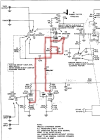
The manual is either incorrect, or HK intended to use exactly the same equalization for the TAPE input and the PHONE input with RIAA selected. See the schematic excerpt with the equalization-determining negative feedback path highlighted. Note that switch S3a controls the feedback path while S3b only controls which input is applied to the grid of V4a. When the TAPE input is selected, the contacts are rotated one position clockwise, which connects the output from the plate of V4b to the cathode of V4a where it provides negative feedback since it is in phase with the input. If the RIAA PHONO input is selected, the contacts (of S3a) are rotated two positions clockwise. In this case, the exact same feedback path is used as when tape is selected. Not until the contacts are rotated three or four positions clockwise is the feedback path altered. As you can see from the schematic notation, there are a total of five selectable positions with positions 3 to 5 dedicated to the PHONO input.

I also have Bode plots of the amplifier connected to the TAPE input and to the PHONO/RIAA input. The responses are identical.

hk_pc200_schem_excerpt.png
 
I'm not certain but I think that, compared to PHONO, the TAPE position adds (or is supposed to add) R1 in parallel with C2, changing the equalization.
 
Last edited:
I'm not certain but I think that, compared to PHONO, the TAPE position adds (or is supposed to add) R1 in parallel with C2, changing the equalization.
On my unit, R1 is added in parallel with C2 when the Function switch is rotated fully clockwise, to the "LP" position (which is PHONO input). This is also how I interpret the schematic. Note that S3 is shown in the "TUNER" position on the schematic and rotates clockwise through four additional positions in the following order: TAPE, RIAA(phono), AES(phono), and LP(phono). R1 is then selected in the fully clockwise position.

It does seem surprising that both the TAPE input and the RIAA phono input would share the same equalization, but there you have it.
 
yeah each position on that switch changes the total amount of capacitance, so the EQ curve will change. If the switch isn't making good contact or the cap(s) are bad, it won't work as expected though. How accurate the EQ curve is would be a different question. Off-value parts skew that, and frankly some of them were never that accurate to begin with.

but its definitely not going to be flat, or at what we'd consider to be a "normal" sensitivity level. Ballpark of 5mv would give you full output rather than 300mv or whatever the other inputs are.
 
yeah each position on that switch changes the total amount of capacitance, so the EQ curve will change. If the switch isn't making good contact or the cap(s) are bad, it won't work as expected though. How accurate the EQ curve is would be a different question. Off-value parts skew that, and frankly some of them were never that accurate to begin with.

but its definitely not going to be flat, or at what we'd consider to be a "normal" sensitivity level. Ballpark of 5mv would give you full output rather than 300mv or whatever the other inputs are.

Of the five positions on S3, the first one bypasses the preamplifier and connects the TUNER (AUX) input to the amplifier. The second and third one use the same EQ curve, selecting either TAPE or PHONO as the input. The remaining two change the EQ curve to AES (which appears to be relatively flat) or LP. From what little reading I've done on the subject, records of that era were recorded with a number of different EQ curves.

10mVRMS is enough for the preamplifier to drive the amplifier to its full rated output. I had no trouble using 30mVRMS. However, if you go up to 100mVRMS or more, you may overdrive the preamplifier and get a badly distorted output as a result. Unfortunately, if you use the TUNER (AUX) input, you will need a lot more power -- at least 2VRMS -- to drive the amplifier to its rated output.

I've tested all of the R's and C's in the EQ networks. In the worst case, a capacitor read 20% below its marked value. Most of the other parts are fairly close. I tested many of the other parts on the board, too. Only a handful have drifted appreciably and only a couple are in parts of the circuit that would significantly affect performance.

The bottom end of the preamplifier Bode plot is fairly flat when AES is selected as can be seen here:

pc200_preamp_aes.png

Things don't look quite as good if we look at the full audio spectrum of both the preamplifier and amplifier, but it's not awful. This is with the TREBLE control adjusted to the 2 o'clock position which gave me the flattest response and the output was driving 1 watt into an 8-ohm resistor:

pc200_all_aes.png

I'm not sure what is happening above 10kHz, but it's not too far off its specifications up to that point. Maybe things will improve after I replace a couple of parts that have drifted and give the PC board a bath to clean off some of the grime that has accumulated over the decades.
 
I accept your description of the EQ portion of the function selector switch.

I did some calculating and the circuit should produce a decent approximation (by standards of the day) to RIAA equalization in the 2nd and 3rd switch positions when the rolloff switch is set to its 3rd position. I did have to guess the value of the rolloff cap (860p or 1n) in that position. It is not legible in my schematic. At least for the model, including the rumble filter seemed to improve fildelity to the RIAA curve.

Adding in the 220k resistor across the 4.7n cap (5th switch position) seems to effectively implement a pole at ~100Hz---although mathematically the situation is more complicated due to there being a number of low frequency poles.

Shorting the 4.7n cap (4th selector switch position) kills the RIAA zero at ~500Hz (moves it to the origin, actually), leading to the near flat low frequency response that you measured.
 
Last edited:
I accept your description of the EQ portion of the function selector switch.

I did some calculating and the circuit should produce a decent approximation (by standards of the day) to RIAA equalization in the 2nd and 3rd switch positions when the rolloff switch is set to its 3rd position. I did have to guess the value of the rolloff cap (860p or 1n) in that position. It is not legible in my schematic. At least for the model, including the rumble filter seemed to improve fildelity to the RIAA curve.

Adding in the 220k resistor across the 4.7n cap (5th switch position) seems to effectively implement a pole at ~100Hz---although mathematically the situation is more complicated due to there being a number of low frequency poles.

Shorting the 4.7n cap (4th selector switch position) kills the RIAA zero at ~500Hz, leading to the near flat low frequency response that you measured.
That makes sense. The Rolloff switch 3rd position reads "12" and is in the color red, which apparently denotes a "standard" configuration. My schematic indicates 1000pF for the capacitor in this position. I seem to recall that in this position, there is significantly more high frequency rolloff than shown in the 20-20kHz Bode plot above too.

I discovered that output capacitance from the plate of the second triode in the preamplifier to ground measured 325pF, which explains why I'm seeing so much gain roll off above 10kHz. I calculate the output impedance for that tube at around 50k which when combined with 325pF gives a pole at 9800 Hz. I snipped C3 out of the circuit and the situation improved significantly with the pole moved up to over 14 kHz.

I'm looking at the frequency response of the entire amplifier now and there is a peak occurring around 12 kHz which is anywhere from 2-10 dB above the baseline depending on how much power the amplifier is putting out. All of the Rs and Cs in the main negative feedback loop are within spec when I test them. I'll do some sensitivity testing to find out more, but maybe some of the old C's in the feedback loop suffer from capacitor voltage dependency.
 
I've replaced most of the capacitors in the HK Prelude (except for the electrolytics which are fine). I used film capacitors. Small differences were noted in the frequency response and distortion (not always better, either). The peak on the high frequency side has remained, although I believe it is likely related to the output transformer. At first I thought it may be interwinding capacitance in the primary, but that doesn't explain its dependence on output power -- higher power levels cause more peaking. Also potentially relevant are the much higher distortion levels at 10 kHz with higher power levels. Much of the distortion appears to be 2nd harmonic distortion which surprises me given that this is a push-pull amplifier.

I just dropped a matched pair of 6V6GT tubes in the amplifier to see if that made any difference. The imbalance in plate voltages is now just 0.2V out of 315V with no drive applied. This has improved the peaking somewhat. I now have to turn the Treble control up a bit in order to see the peak. The amplifier gets no where near the specification of +/- 1dB from 20-20kHz. Perhaps it never did -- I think test equipment to display this graphically wasn't available until around 1954 so unless their lab was state-of-the-art at the time they would have had to manually test the amplifier at discrete frequency points. Best I can get is about +/- 2dB from 20-20kHz. Distortion is OK through the midrange but goes through the roof at higher frequencies with higher power levels.

It's tempting to replace the output transformer with a modern unit by Hammond, but that seems to cross the line from a restoration into something else.
 
Feed signal in directly to the power amp, bypassing all of the controls and see what the response looks like.
 
Feed signal in directly to the power amp, bypassing all of the controls and see what the response looks like.
There is an AUX input (Tuner) that bypasses the preamplifier. This bypasses the equalization circuitry, but the Treble and Bass controls are still present in the negative feedback path from the secondary of the output transformer back to the phase splitter.

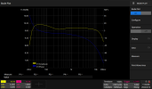
Meanwhile, here is the frequency response of the amplifier, with the preamp bypassed and with the output power set to 5 watts at 400 Hz. I set the Treble control to 2 o'clock to reduce significant rolloff above 7-8 kHz or so. It is certainly better than when the preamplifier is used, although it requires around 1.5VRMS to get full output from the amplifier through the Tuner input. It does look like it meets the manufacturer's spec of +/- 1dB from 20-20kHz in this configuration!

SDS2504X Plus_PNG_204.png

The high frequency distortion is slightly improved with the preamplifier bypassed. Instead of 5.1% THD at 5W it is now 4.3%. Looking at the waveform on an oscilloscope shows a sine wave that looks more like a rounded triangular wave -- a slew rate limited sine wave.
 
That bypasses the phono stage, it doesn't bypass the line stage. I mean feed the power amp directly, just the stuff that lives within the global feedback loop. No tone controls, etc. Don't have a schematic but commonly the volume control outputs directly to the power amp. Feed signal in there and I'd wager you get something nice and flat.

I also wouldn't be remotely surprised if those stock transformers are superior to anything you can buy now.

If the treble needs to be turned that far up, fair bet there are off-value parts in the line stage. The pots themselves are a big part of the response.
 
That bypasses the phono stage, it doesn't bypass the line stage. I mean feed the power amp directly, just the stuff that lives within the global feedback loop. No tone controls, etc.
There is no line stage. Tone controls are within the power amp feedback path. The volume control is fed directly from the tuner input (assuming the rumble filter is defeated) and while the volume pot is tapped, another switch defeats contouring there. From the wiper there is then only a small cap (10p?) in parallel with 100k on the path to the (12ax7) driver's grid---or maybe not as it has been scratched out on the copy of the schematic I have.

Note despite 6V6 indicated in the manual text, my schematic shows the EL84 version.
 
The schematic that is publicly available is, I believe, the 1959 version of the amplifier which used EL84s. I have the 1957 version which uses the 6V6 tubes. I downloaded a copy of the 1957 schematic from RadioMuseum.org, but I don't know if it is OK to post it here so if anyone wants it, you can go there and get it after giving up your email address.

As Audiotemp said, the tone controls are within the main amplifier feedback path, which is itself directly fed by the Tuner input provided the rumble filter is off. The volume control pot (1MEG) has a double tap, with the top tap going DIRECTLY to the grid of a 12AX7 and the lower (fixed) tap which is supposedly 200k above the lower portion of the pot, but on my amp it is actually 275k above. The bottom of the pot goes to ground. The fixed tap goes via a 68k resistor to the Contour control, which is a 4700pF capacitor to ground and then depending on the switch position, either a direct connection to ground, a connection through a 47k resistor to ground, a connection through a 47k resistor and a 270k resistor to ground, or no connection. As you would expect, this primarily affects the lower end of the frequency response.

I have limited personal experience with vintage tube HiFi amplifiers, this being the first unit I've spent much time with. So I have no basis for knowing whether a modern transformer like one manufactured by Hammond would be superior to the one Harman Kardon installed back in 1957. Generally speaking, components have become smaller and better than what was used 67 years ago, but I'm sure there are exceptions and maybe audio output transformers are one of them? I do know that when I replaced all of the capacitors in the amplifier that were either coupling capacitors or part of a feedback loop with modern film capacitors, the frequency response improved and the THD decreased except at the high end of the spectrum.

Maybe this is about as good as this old HK PC200 is going to get?
 
Back
Top Bottom