• The move to the new server is done. There are some software and database maintenance updates in process. This has us passing the hat around to help out. We appreciate any donations. Seriously, even a dollar helps. The payment page may be found here - https://www.audiokarma.org/support.html

Eric Engineering - Tuner - model 357

Dig22

Active Member
Hi,

I haven't found much info on this tuner. Does anyone have any schematics or Info or anything?

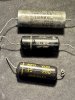
I swapped out the few capacitors I had on hand, but when I started raising voltages in increments of 30 volts every 30 minutes on a Variac, the transformer got really hot around 60 volts. So I stopped. I'll get the other electrolytic caps and try again, but is there something else I should look for?

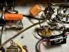
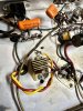
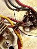
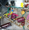
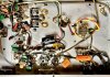
I've attach a few photos including the parts I swapped.

I appreciate any advise. Thanks!

IMG_8497.jpg IMG_8499.jpg IMG_8498.JPG
IMG_8496.jpg IMG_8500.jpg 800px-Vintage_Eric_Engineering_Model_357_Mono_FM_Tuner,_Made_In_USA_(15098903074).jpg


800px-Vintage_Eric_Engineering_Model_357_Mono_FM_Tuner,_Made_In_USA_(15098903074).jpg IMG_8496.jpg IMG_8497.jpg IMG_8499.jpg IMG_8498.JPG IMG_8500.jpg
 
Last edited:
Register to hide this ad
Aside from any shorted windings in the power transformer (rare), you most likely have a shorted can capacitor or shorted selenium rectifier/diode.

What is your level of expertise because an ohm meter will be able to tell you this. A shorted rectifier will show 0 ohms in either direction of the meter probes. A shorted can capacitor will show the same.
 
Last edited:
Aside from any shorted windings in the power transformer (rare), you most likely have a shorted can capacitor or shorted rectifier/diode.

What is your level of expertise because an ohm meter will be able to tell you this.

Thanks for responding. Regarding my expertise, between 1 and 10, I'm a solid 1. I have fixed many tube amps (I'm always careful) but I'm still a monkey-see-monkey-do guy following instructions.

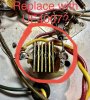
I have a meter. I need one more capacitor for the cap can than I can swap all. But with hat in hand, without a manual I can't identify the rectifier diode.... which one is it?
 
Golden thingy with the heat fins.

A single UF4007 diode should suffice. Most people replace these anyway even if good because when or if they let go, they stink.........maybe even worse than a skunk.:rflmao:
 
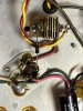
something doesn't look right about how that rectifier is hooked up. Maybe I'm not following the leads right, but it looks like the red lead from the transformer connects to the can cap's grounded outer ring. The yellow lead appears to go to the rectifier end that has a wire going to a grounded terminal on a terminal strip next to it. If thats what I'm looking at, thats a dead short across the transformer.
 
interesting, that one does not show the jumper from the yellow lead to the grounded terminal strip, which is how I'd expect this to be hooked up.
 
Golden thingy with the heat fins.

A single UF4007 diode should suffice. Most people replace these anyway even if good because when or if they let go, they stink.........maybe even worse than a skunk.:rflmao:

Thanks! I think the rectifier smell is what alerted me to the transformer heating up.
 
something doesn't look right about how that rectifier is hooked up. Maybe I'm not following the leads right, but it looks like the red lead from the transformer connects to the can cap's grounded outer ring. The yellow lead appears to go to the rectifier end that has a wire going to a grounded terminal on a terminal strip next to it. If thats what I'm looking at, thats a dead short across the transformer.

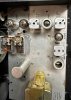
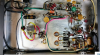
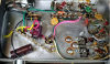
Here are some photos of my unit from different angles

IMG_8507.jpg IMG_8508.jpg IMG_8509.JPG

here are photos of a another same model unit I found on line -- before and after fixes

1_RetroVoltage - Before.png 2_RetroVoltage - After.png 3_RetroVoltage - Saftey Cap.png
 
Golden thingy with the heat fins.

A single UF4007 diode should suffice. Most people replace these anyway even if good because when or if they let go, they stink.........maybe even worse than a skunk.:rflmao:

IMG_8502.jpg just double checking this is the rectifier to replace.
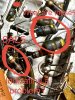
IMG_8504.jpg All the 10K resistors by the 6AL5 look damaged to me. Maybe to much heat? I can swap them, but does that indicate a possible problem somewhere? And what are the bloated resistor-like parts (also circled in photo)?
 
View attachment 2878562 just double checking this is the rectifier to replace.
View attachment 2878563 All the 10K resistors by the 6AL5 look damaged to me. Maybe to much heat? I can swap them, but does that indicate a possible problem somewhere? And what are the bloated resistor-like parts (also circled in photo)?

I believe that those are not resistors? What does the schematic say?

Your "found online" pics do show the golden rectifier has been replaced by a black diode which is most likely a 1N4007 or UF4007 diode.

Also, this tuner reminds me of a DeWald.
 
Last edited:
Here are some photos of my unit from different angles

View attachment 2878550 View attachment 2878551 View attachment 2878552

here are photos of a another same model unit I found on line -- before and after fixes

View attachment 2878553 View attachment 2878554 View attachment 2878555

notice on the second group of pictures there is no wire from the end of the rectifier where the yellow wire attaches going to the terminal strip like there is on yours. That wire on yours goes to ground. It just doesn't look right to me. I'd try cutting it loose and see if it starts working.

Were these kits? No guarantees a kit was assembled correctly.


the lumpy things are capacitors, not resistors. Leave them alone unless you know they are bad and know you have a way to re-align this.
 
notice on the second group of pictures there is no wire from the end of the rectifier where the yellow wire attaches going to the terminal strip like there is on yours. That wire on yours goes to ground. It just doesn't look right to me. I'd try cutting it loose and see if it starts working.

Were these kits? No guarantees a kit was assembled correctly.


the lumpy things are capacitors, not resistors. Leave them alone unless you know they are bad and know you have a way to re-align this.
 
notice on the second group of pictures there is no wire from the end of the rectifier where the yellow wire attaches going to the terminal strip like there is on yours. That wire on yours goes to ground. It just doesn't look right to me. I'd try cutting it loose and see if it starts working.

Were these kits? No guarantees a kit was assembled correctly.


the lumpy things are capacitors, not resistors. Leave them alone unless you know they are bad and know you have a way to re-align this.


Bingo! I removed the wire from the yellow rectifier lead to ground and the radio works like a champ! Thanks! I'll continue recapping it. I'll run it awhile to check if the transformer is still heating up.

What do you think about using a X1Y2 safety cap? What value would I used to replace the .033mdf 600VDC cap?
 
I believe that those are not resistors? What does the schematic say?

Your "found online" pics do show the golden rectifier has been replaced by a black diode which is most likely a 1N4007 or UF4007 diode.

Also, this tuner reminds me of a DeWald.

Thanks for responding. I don't have schematics and I have no info other than the link in this post.
 
Good eye Gadget. My eyes are getting old. That was a direct short for the power transformer so it should run cool and normal now.
 
What do you think about using a X1Y2 safety cap? What value would I used to replace the .033mdf 600VDC cap?

0.033uf in an X1Y2 is just fine, probably going to be rated 250 vac if you're looking to replace either an across the line or line to chassis cap.
 
Back
Top Bottom