Dig22
Active Member
0.033uf in an X1Y2 is just fine, probably going to be rated 250 vac if you're looking to replace either an across the line or line to chassis cap.
Thanks Gadget. I'm really happy this as na easy fix.


0.033uf in an X1Y2 is just fine, probably going to be rated 250 vac if you're looking to replace either an across the line or line to chassis cap.
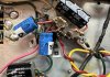
I believe that those are not resistors? What does the schematic say?
Your "found online" pics do show the golden rectifier has been replaced by a black diode which is most likely a 1N4007 or UF4007 diode.
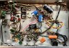
Also, this tuner reminds me of a DeWald.

I also thought of Eico but most Eico's I have seen had more of a golden color to them and not so red looking. Could be the light. This tuner also reminded me of a certain Harman-Kardon.The tuner looks a lot like an Eico on the outside.


I had an Eico HFT-90 for years. The tuning eye was cool. I used it in a mono system in my shop with a small 6V6 PP amp.I also thought of Eico but most Eico's I have seen had more of a golden color to them and not so red looking. Could be the light. This tuner also reminded me of a certain Harman-Kardon.
Those Eico's (the HFT-90) had a really cool tuning dial which was like a tuning eye type of tube attached to the dial string. I had one but got rid of it. My Knight KG-50 has the same type of tuning eye and I ainta never getting rid of this one.
The UF is a bit faster but for this it doesn't matter much. Did you have it facing the right way? If not the caps get neg voltage and they won't like it.
Will also need a resistor bigger than the 10 ohm to keep voltage right
Did you have the diode connected so the white band was pointing towards the can capacitor?
You can probably get away with using the original selenium rectifier and it may never give you any problems.
The tuner looks a lot like an Eico on the outside.

Thanks! There's a 100 ohm on there. Looks original. Is that ok?
probably going to need to be larger in order to keep the voltages right. Silicon has much lower drop than selenium
or honestly if the stock rectifier is working, leave it be. personally I think people get way too focused on these things. They aren't great but in low current demand applications like this they don't tend to be all that troublesome.
probably going to need to be larger in order to keep the voltages right. Silicon has much lower drop than selenium
or honestly if the stock rectifier is working, leave it be. personally I think people get way too focused on these things. They aren't great but in low current demand applications like this they don't tend to be all that troublesome.

This is exactly why I say to put it back or leave it alone. I have radios with the original selenium with no problems whatsoever.