• The move to the new server is done. There are some software and database maintenance updates in process. This has us passing the hat around to help out. We appreciate any donations. Seriously, even a dollar helps. The payment page may be found here - https://www.audiokarma.org/support.html

Fender M-80 Bass Amplifier making distorted output

Thanks. I have now replaced the faulty Zener diode, and the reading on the DMM is satisfactory at the Zener; however, the amp is still producing the distorted output. I will include photos of the scope readings (below).
I am focusing primarily upon the power amp push/pull section of the circuit, and I am going in descending order of the test points, starting at test point 19.

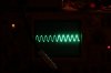
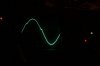
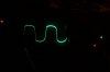
Here are tp19 and tp18. As far as the test points go, these are the only test points that show any mis-shapen waves.
TP19 (below) has a flat topped peak. This is at the Line Output, after the output at TP18 has gone through the 4.7Kohm, 1Watt resistor, R121..
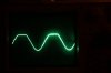
02_tp19.JPG


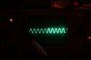
TP18 (below) has what seems to be a disjointed peak. This is the signal, just before L1. Out of curiosity, what kind of component is L1? It looks like a large disc capacitor.
Would this wave distortion of the peak indicate the push section is faulty? Thanks.
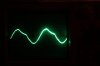
03_tp18.JPG
 
TP 18 and TP 19 in your schematic are basically the same, it's the output after the power amplifier. I think you need to go back to TP15, the OP amp output, to see how the signal is before the power amp, to see if the power amp is OK or not. Obviously the top half is bad, but it could be just amplifying a bad signal.

BE CAREFUL, the manual indicates test point at the IC pin, but you can measure at the 100K resistor or at the 2.2uF capacitor. Measure before and after that coupling capacitor.

Disable the chorus or any other effect.

L1 is an inductor, a wire coil.

Are the + and - voltages OK at the power amp section?, now that you replaced the Zener? The schematic calls for -50V +50V and +16V and -16V feeding the OP amps.

Are you using the right input signal (I mean voltage of your sine wave)
 
Last edited:
Thanks for your input and help.
Regarding the coupling capacitor, is C40 the 'coupling capacitor'? Thanks.
That is my next step in testing.

The chorus has been disabled, and only the specifications listed at the bottom of the schematic have been active (e.g. chorus rate to 10 and chorus depth to 0, etc).

My mistake regarding L1. The 'mystery' part in question is actually TH-1. That is the large disc component, which looks like a disc capacitor.

I will double-check the + and - voltages at the power amp section and report back.

Regarding your last question, how can I confirm that I am using the correct input signal (sine wave voltage)?

Thanks
 
Thanks for your input and help.
Regarding the coupling capacitor, is C40 the 'coupling capacitor'? Thanks.
That is my next step in testing.

The chorus has been disabled, and only the specifications listed at the bottom of the schematic have been active (e.g. chorus rate to 10 and chorus depth to 0, etc).

My mistake regarding L1. The 'mystery' part in question is actually TH-1. That is the large disc component, which looks like a disc capacitor.

I will double-check the + and - voltages at the power amp section and report back.

Regarding your last question, how can I confirm that I am using the correct input signal (sine wave voltage)?

Thanks

Yes, I was referring to C40, the 2.2uF after TP15.

I can't find "TH-1" in the schematic, but given your description and the letters "TH", it makes me think in some "THermistor", "THermal something". A pict will help.

The schematic says to feed 1KHz, 40mV AC at the input, TP1 ( I assume RMS Volts). That signal should give you 477mV AC at TP15, with all the controls set as detailed at point #5 (all controls to 12 o´clock)

I want to discard that you are simply saturating the input.

Just confirm the signal at TP1, and check it at TP15. That way we'll discard half of the amplifier. Then, move to the bad half.

I'd test the amp UNLOADED, no load at the output, until you get a good signal.
 
Thanks

The TH-1 component is pictured in the 3 photos below. Thanks for any help in identifying... :)
th1_a_feb21_2016 copy.jpg
th1_b_feb21_2016 copy.jpg th1_c_feb21_2016 copy.jpg
I've gone back and have been re-checking the input level.
I re-adjusted the signal generator, as it was, indeed, saturating the input.
The scope readings now look accurate, and I've posted them for verification, along with volts/div settings.

the first photo is of the scope reading, after signal generator re-adjustment of output, at tp1.
Scope setting of 50m volts/div (AC)
tp1_feb21_2016 copy.jpg

2nd photo is of tp15.
Scope setting of .5 volts/div (AC)
tp15_feb21_2016 copy.jpg

3rd photo is of tp19
Scope setting of .5 volts/div (AC)
tp19_feb21_2016 copy.jpg
4th photo is of tp18
Scope setting of 5 volts/div (AC)
tp18_feb21_2016 copy.jpg
 
Good news! !!

Do the levels match the schematic? If so, I'd say try it with a load, and then just play some bass guitar!!!
 
Good news! !!

Do the levels match the schematic? If so, I'd say try it with a load, and then just play some bass guitar!!!

Thanks.
The levels do match the schematic, but when the bass is played, even at low levels, it's still distorted. I may record the sound and upload, as well.

When the input was saturated (reference to the previous post - Fender M-80 Bass Amplifier making distorted output), there was that problem with the top part of the wave, only.
No components have been changed since those readings were taken. It seems that a saturated input would clip on both top and bottom, is that correct?
 
the test by now is OK. but you hear distortion anyway, that's not OK.

Try the amp with the same signal level (a bit more perhaps, you are feeding less than 100mV Peak to Peak, and 40mV RMS would be 112mV peak to peak, so slightly passing the "50mV/div", to have more than 100mV peak to peak), and with a 8 ohm load at the output. You don't need to crank up the volume (that will overheat the resistor) since you hear distortion at low levels. We need to find that problem. Sometimes it's just one OP amp that went "tired".

Please, once you confirmed the singal levels, zoom on your scope, modify the horizontal and vertical scale to have just one full wave filling the whole screen. I wan to see if you have crossover distortion (a "dent" where the sine wave pass from positive to negative)

You are right, the signal should clip symmetrically top and bottom. Try (unloaded by now) the same input signal level, and increase the volume control to see if you reach the clipping point while monitoring the signal. If the signal clips at both ends, then you could try increasing the input level, and check at TP 15 (before the power amp) to see if the preamp clips symmetrically. If we find wich half is clipping in a bad way, then we can narrow the search.

Regarding the Thermistor:
This Fender service manual
http://bmamps.com/Schematics/fender/Stage_100,_160_DSP_Service_Manual.pdf
at page 8, refers to "**THERMISTOR 2.5 ohm 8A C30-19", wich match the C30-19 numbers printed on your part.
 
Last edited:
Try the amp with the same signal level (a bit more perhaps, you are feeding less than 100mV Peak to Peak, and 40mV RMS would be 112mV peak to peak, so slightly passing the "50mV/div", to have more than 100mV peak to peak), and with a 8 ohm load at the output. You don't need to crank up the volume (that will overheat the resistor) since you hear distortion at low levels. We need to find that problem. Sometimes it's just one OP amp that went "tired".

Thanks.
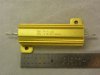
I'm in the process of making a load, using an 8ohm, 50w resistor.
Will I need several of these 8ohm, 50w resistors in series, along with speaker wire?
The model I'm using is "Dale RH-50".8ohm_50w_resistor.JPG
 
I think one 50W resistor is enough for a test. Anyway don't let it at full power for long time, since the Amp is not reliable yet, and you hear distortion at low levels.

What I'd do: with the right undistorted input signal, Amp unloaded, increase volume pot until clipping at the output. Check if it's symmetrical. Turn volume down, back to 12 o' clock.

Then, test the preamp, monitor at TP 15, increasing the input signal until clipping the input, and check if it's symmetrical. If not, start measuring at each OP Amp input and output. There will be one where the input is OK and the output is bad.

I wouldn't connect a dummy load until the Amp performs ok unloaded.

When loaded, do brief tests at high power output. Don't stress the Amp for long times until you trust it.
 
Thanks
Then, test the preamp, monitor at TP 15, increasing the input signal until clipping the input, and check if it's symmetrical. If not, start measuring at each OP Amp input and output. There will be one where the input is OK and the output is bad.

In increasing the input signal, would that be increasing the output volume of the signal generator or the amplifier volume?
 
I mean increase the signal generator level, to reach the clipping point at the input. Do all this UNLOADED, we don't need to stress the amp to see this.

Anyway, do both tests.We want to see if the problem is at the preamp, or at the power amp. I suspect an OP amp going bad, but it could be some issue at the power amp too...
 
Thanks

I've gone back and have been re-checking the input level.
I re-adjusted the signal generator, as it was, indeed, saturating the input.

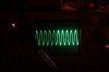
photos 1, 2, and 3 are of tp19 (just different camera exposures to give a variety of detail).
(note: same correct setting as in previous post, but with wave zoomed to show detail of just one peak
cycle. There appears to be the 'denting' or crossover distortion. volume was at 12 o'clock.)
Scope setting of .1 volts/div (AC)
tp19_a_feb25_2016 copy.jpg tp19_b_feb25_2016 copy.jpg tp19_c_feb25_2016 copy.jpg

photos 4 and 5 are of tp18.
Scope setting of 2 volts/div (AC)
tp18_a_feb25_2016 copy.jpg tp18_b_feb25_2016 copy.jpg

photo 6 is of tp18.
Scope setting of 5 volts/div (AC)
tp18_c_feb25_2016 copy.jpg

photo 7 is of tp19
(note: increased volume until the 'dents' 'broke' and became more pronounced)
Scope setting of .2 volts/div (AC)
tp19_vol_increase_a_feb25_2016 copy.jpg


(CONTINUED IN NEXT POST)
 
Last edited:
photo 8 is of tp15
(note: increased output of signal generator until distortion occurred. Does this appear symmetrical? )
Scope setting of 2 volts/div (AC)
tp15_sig_gen_vol_incr_feb25_2016 copy.jpg
 
the last pict seems OK. Anyway, I'd try just to reach the clipping point, the point where the sinus gets with a little flat top.

As for the rest, I see it's not the usual "crossover distortion". This is a dent but not at the half of the wave (google "crossover distortion").

Do the signal looks fine at TP15? Try to zoom on that TP15. All this picts are TP 18 and 19, at the output. We need to see if the signal is OK before getting into the power amp section.
 
Last edited:
The last post (post 34) (with the single photo - photo 8) is of tp15. I will provide a zoom of that one this evening.
Thanks.
 
We need TP15 without clipping, one complete sine wave on the full screen.

Then, you could pict TP15 at clipping point (when it starts to clip)
 
Thanks.
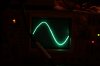
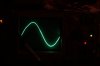
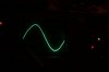
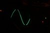
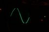
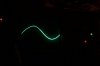
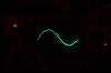
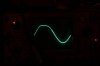
photos 1 and 2 are of tp15 (no clipping and when it starts to clip).

photo 1
Scope setting of .2 volts/div (AC)
tp15_feb25_2016_pm_a copy.jpg


photo 2 (clipping)
Scope setting of 1 volts/div (AC)
tp15_feb25_2016_pm_b copy.jpg
 
Well, There is no dent, but that's not symmetrical.... To me, this indicates a problem at some OP Amp or a problem with the +- Voltage feeding the OP amps.

Anyway when the signal is OK, no clipping, the output was distorted with that "dent".

I'd do 2 tests: try to trace this asymmetrycal clipping, monitoring the signal along the preamp, at each OP Amp input and output, and trace that "dent" at the power amp, with the good sine wave. I'd monitor the Driver's base, and the output transistors base. The base receives the signal and the transistors let the current flow following that signal pattern. If the signal at the base looks fine, perhaps the transistor is bad. Or some feedback network is introducing this...
 
I'd do 2 tests:..... I'd monitor the Driver's base, and the output transistors base. The base receives the signal and the transistors let the current flow following that signal pattern. If the signal at the base looks fine, perhaps the transistor is bad. Or some feedback network is introducing this...

Thanks.
When you mentioned "Driver," what were you referring to?
 
Back
Top Bottom