• The move to the new server is done. There are some software and database maintenance updates in process. This has us passing the hat around to help out. We appreciate any donations. Seriously, even a dollar helps. The payment page may be found here - https://www.audiokarma.org/support.html

Fender 'Super -Amp' 5F4 build

Dandy

Addicted Member
I recently bought an old guitar amp chassis for the excellent audio output transformer on it. Looking more closely at the chassis and components, and drawing the schematic, I see it is quite similar to the Fender Super-Amp 5F4. Schematic for that amp here: http://i.imgur.com/SOSZRvJ.gif

On mine, the power supply has been modified (no choke and bigger filter and reservoir caps and the bias arrangement is different). I've cleaned it up, reattached a few components that had come loose and the amp is working well with a replacement output transformer taken from an organ amp that used two 6L6s in push-pull.

What I'm wondering is whether it is worth converting to the classic Fender Super-Amp circuit, or even to the Super Reverb circuit? I strum an acoustic guitar badly, but guitar amps are new to me. I'm rebuilding this for my adult daughter who does play but is not here to consult. Any advice from Fender owners?
 
Register to hide this ad
The Super is a pretty nice amp... a friend-of-a-friend of mine has one. Very similar to the 5F6 Bassman that of course everybody ended up copying. Main difference is the phase inverter and output tubes (cathodyne + 6L6G on the 5F4, long-tail pair + 5881 on the 5F6). The tone controls are a little different, too.

Honestly, if what you have is working well, I don't necessarily see much advantage to making it exactly match the 5F4, especially if the main difference you're seeing is just in the power supply. If the power rails are capable of supplying the necessary juice, that's what's important, unless you're looking to replicate EXACTLY the supply sag of the 5F4 (there would be some, because it uses a 5U4). I really suppose it depends on your daughter's playing style! It sounds to me like the supply has been stiffened up a bit, which would mean less compression at high power. You're unlikely to hear much difference except at pretty loud volumes (unless you have a power soak on your speaker cabinet, of course :-) )

(Yes, I totally understand that in the world of guitar amps, power supply topology can make a difference... I myself made sure to NOT upgrade the power supply during my on-going restoration of my Silvertone 1484 specifically because the weak-sauce power supply contributes to the sound of that amp.)

Would love to see photos.
 
Thanks for your informed advice thorpej. As I've never used a Fender Super or even seen one before, I'm sort of reverse engineering this one. Actually Mark Lanegan has a gig in the cathedral where I work tonight and I chatted to him earlier today about the Fender Super Reverbs that he was miking up for the show. These were the first ones I've ever seen.

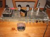
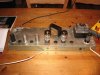
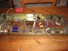
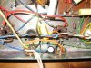
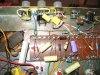
Here are some pics.
Fender 393.jpg Fender 394.jpg Fender 395.jpg Fender 399.jpg Fender 400.jpg Fender 402.jpg

The amp is not very pretty and looks as if it was built as a clone on an old chassis (see the 4 blocked socket holes in the second pic) about 10 years ago. I don't know where the PT came from, but it is up to the job. I'm using a 5AR4 rectifier at the moment, and haven't tried a 5U4 yet. The original builder looks as if he/she knew what they were doing, but it may have been tweaked by a later owner. I bought the amp for the Partridge OPT, which was the special upgrade offered to the high quality Parmeko transformer offered for a Sterns Mullard 5-10 in the late 1950s.

If you are interested in checking out the changes to the original I can redraw my schematic more tidily and post it. The changes are to the cathode (bias?) connections to V1, the feedback to cathode 1 on V3 and the bias arrangements for the 5881s, and the power supply (no choke). At present the pot on the left in the first picture and the last one doesn't seem to affect the sound. Would this be the one marked 'Presence' on the schematics? The actual pots are old and I can't read all the values. I do want to get the tone controls right.
 
Last edited:
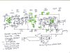
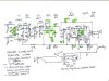
I now attach my schematic of the amp as it is at present, with the changes to the original Fender schematic marked in green.

The two questions I have are: (1) how do I get the tone section right? It is very different from the orginal--the 'presence' pot (RV5) does nothing as it is configured, and the bass pot doesn't do much. And (2) do I need that feedback loop from the speaker back to cathode 1 of V3? I've read that earlier models had a cathode bias arrangement like this one, so that seems fine. I've no experience of guitar amps, so would value any comments on the tone section.

Fender schematic003.jpg
 

Attachments

  • Fender schematic003.jpg
    Fender schematic003.jpg
    83.8 KB · Views: 4
Yah, pretty close. Looks like instead of the normal Fender Hi / Lo arrangement, there's a normal and a bright input? Seems like it also has a much higher level of negative feedback. I don't doubt that the presence control doesn't work that well -- it's not in the feedback loop, which is where it's usually most effective. I don't know the secondary impedance of the original 5F4 OT, although I believe the primary side was in the ballpark of 6K (6.4K maybe?). Anyway, that ratio along with the feedback divider is going to determine how much feedback is applied. I would experiment with that. What is the primary / secondary of the OT that you installed in the chassis after you harvested the one it came with?

As far as the tone controls go, I'd try just replicating the original 5F4 tone stack. Although be aware that if you plug into the bright channel (the one with the 0.5uF cathode bypass cap), the bass control probably is not going to change the sound very much!
 
Last edited:
Thanks for the advice. It's great having an informed second pair of eyes on an unknown amp, though I'm moderately pleased that I recognised it for a Fender derivative. I redrew the schematic following the Fender design to allow for easy comparison. :)

I'll check the replacement OT primary/secondary ratio and primary impedance. I had no info about the organ amp I pulled it from, except that it was originally used with two 6L6s in push pull. I'll also redo the tone stack. Then it's just a matter of safety: IEC connector for the mains cable, better HT wiring, etc.
 
BTW, if it were me I'd make a couple of other changes:
  • Fuse on the DC part of the HT is a really bad idea, in general. When the fuse blows, you risk a big arc across the gap. If you're going to have a fuse on the HT side, do it BEFORE the rectifier, that way the natural voltage drop that happens with AC will suppress the arc. But since you have 2 phase rectifier, you'd need a fuse on each end of the HT winding. But you have a valve rectifier! Those practically never fail short, so I wouldn't even worry about fusing the HT side. Fuse the PT primary, instead. Wire it up: Live -> fuse -> switch -> primary lead. If you get an IEC connector with a built-in fuse holder, this is done for you.
  • Consider getting rid of the standby switch, or at least making it not completely evil. Merlin has a few words on the subject: http://www.valvewizard.co.uk/standby.html
 
Thanks! I haven't built many amps yet, and I need to learn these basics. The fuse was there already, but is easy to move to where it should be. The standby switch isn't there at present, so I'll keep it out. And I'm bookmarking Merlin's site right now!
 
Also, I wouldn't bother replicating the original Fender Hi / Lo input. I don't think I've ever seen anyone use a Lo input... maybe if they had to tame really hot humbuckers or something, but isn't that what the volume control on the guitar is for?? Way better to have the normal and bright channels like what seems to be there in your drawing.
 
I've redone the tone stack, feedback and presence pot, and changed the cathode connections on V1 12AY7 according to the original schematic. It still works (!), but there is a soft buzz, which gets louder when bass and especially treble is advanced. Not yet pulled the OPT to check turns ration and primary imp.
 
I rebuilt the point to point wiring this afternoon to make the layout as close to the Fender original as possible. The layout pictorial is much harder to follow than a schematic without the exact same turret board layout and a different bias arrangement. I was glad of my hand-drawn schematic.

Apart from the buzz from the treble pot that gets louder as it is advanced or the volume is raised, is sounds pretty good. The PT is not original and the voltages are a bit low all round. 6L6s with about 330V on the plates okay?

Now for some fun with building a case.
 
I rebuilt the point to point wiring this afternoon to make the layout as close to the Fender original as possible. The layout pictorial is much harder to follow than a schematic without the exact same turret board layout and a different bias arrangement. I was glad of my hand-drawn schematic.

Apart from the buzz from the treble pot that gets louder as it is advanced or the volume is raised, is sounds pretty good. The PT is not original and the voltages are a bit low all round. 6L6s with about 330V on the plates okay?

Now for some fun with building a case.

Yah, that's certainly not going to hurt a 6L6. The buzzing thing is interesting... does it happen without an instrument plugged in and the input shorted?
 
Yah, that's certainly not going to hurt a 6L6. The buzzing thing is interesting... does it happen without an instrument plugged in and the input shorted?
The buzzing is less without an instrument and the input shorted. But, I also noticed that working the pots a lot reduced it. These were old pots that I cleaned with a sonic jewellery cleaner. I'm going to add some switch lubricant. With the tone pots level, there's no buzz. I'm also using a old, cheap Les Paul copy. I've cleaned its very cheap and nasty pots, but I wonder about the pickups which are certainly not Les Paul
 
My amps pick up a little buzz even with the nice Gibson 'buckers in my Les Paul. You don't even want to know how noisy the single-coil Teisco pickups in my Silvertone 1445 are :-)
 
This is branded Columbus, MIJ, but nothing special. Like this one:

Those are not humbuckers, but single coil pickups in disguise. I wish I could play 'Oh Well' like this young guy.

Thinking of my cabinet build, do you think that I can use two 12" 8 ohm speakers that I have in my stash?
 
Last edited:
Have you measured the output transformer yet? You'll want to make sure you end up with the correct operating point for the output stage given a 4 or 16 ohm speaker load.
 
Output transformer measurements:
Turns ratio 39:1
Impedance ratio: 1521
Thus 6k into 4 ohms, or 12k into 8 ohms.
So, two 8 ohm speakers wired in parallel would work well. At least I think so, given the 330V on the plate of the 6L6s.
 
The RCA 6L6GB data sheet recommends a 9K plate-to-plate primary for cathode-biased Class-AB1, but 6.6K for fixed-bias Class-AB1. Your transformer would be OK for a fixed-biased amp, but the one you have is cathode-biased. It may work fine at 6K with cathode bias, but you're going to want to do a load line analysis and calculate how the bias is going to shift when it enters Class-B territory. If your load line crosses below the knee of the plate curve, that indicates that the screens are going to start sucking up all that current. You may have to add some dropping resistors on the screens to pull the plate curves downwards as the screen current increases to keep the screens from over-dissipating (tube death sucks).

Another option would be to bias it fairly hot so it always stays in Class-A. The RCA data sheet recommends a 5K primary in that case, but the 6K will be OK in that scenario, I think. (Hey, it's a guitar amp after all ... "close enough" is often more desirable than "just right" :) ) Again, a load line analysis would tell you for sure. Just make sure not to over-dissipate the plate :) Your total power in that scenario will probably be limited to 18W or so, but I don't think that would be too far off of what you'd get from a compromised Class-AB1 operating point anyway. Oops, it occurs to me that you might need screen dropping resistors in this configuration, too, because of the slope of the load line is going to be less steep at 6K than at 5K.
 
Back
Top Bottom