• The move to the new server is done. There are some software and database maintenance updates in process. This has us passing the hat around to help out. We appreciate any donations. Seriously, even a dollar helps. The payment page may be found here - https://www.audiokarma.org/support.html

Fezz Titania bias specs

salon1audio

New Member
Hey yall,
Anybody know the bias specs for the Fezz Audio Titania? All black, with triangle transformer covers.
I've tried reaching out to them but no responses. They are based out of Poland, and from what I can tell this was their first model, which is long been revised and replaced.
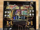
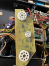
There are 4 trimmers, one for each DT88 tube.
Came to the shop with the left channel blown up.
Thanks
 
Register to hide this ad
Do you know how the output stage is biased? Fixed or Cathode?

The Class the amp was designed to run in?

Push-pull or single-ended design?
 
Class AB1
Push pull

According to google,
"Cathode Bias System: The Fezz Titania uses cathode bias, which offers significant benefits for user maintenance. It is self-balancing, allowing for easy "tube rolling" or replacement without needing to manually adjust bias voltages, even if the tubes are not perfectly matched."

Left channels DT88's and 9 capacitors are shorted/blown up
 
Class AB1
Push pull

According to google,
"Cathode Bias System: The Fezz Titania uses cathode bias, which offers significant benefits for user maintenance. It is self-balancing, allowing for easy "tube rolling" or replacement without needing to manually adjust bias voltages, even if the tubes are not perfectly matched."

Left channels DT88's and 9 capacitors are shorted/blown up
Are there bias potentiometers or some sort of bias adjustment on the unit? This would mean Fixed Biased (and prolly AB1).

Or do you see a large wire-wound resistor(s) hanging off the KT-88 cathode pins? This would mean Cathode Biased (and prolly Class "A").

Thanks!
 
No large resistors on the cathode.
the 560ohm 50W resistors are on the heater pin I think....
Okay, I'll ask a long-distance question ... be sure those 560-ohm resistors are on the heater and not the cathode. And what are the output tubes? Is it a KT-88 or a triode (like a 300B)?

Which resistors and other parts were damaged?
 
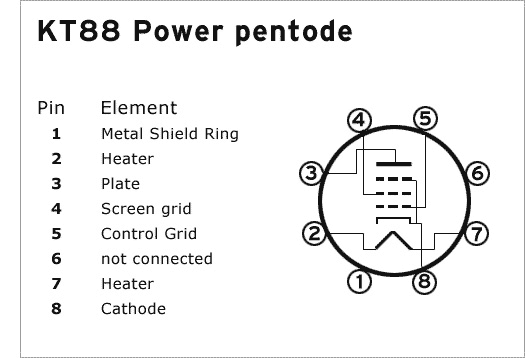
Any chance that the circuit looks like this?

F01-KT88-Amplifier.png


Do you have access to a schematic for your amp?
 
yes! my bad. the large resistors are on the Cathode.
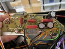
The bottom pins are left2right 8,7,6
8 pin cathode connects by trace to the orange wire that goes to the resistors
 
yes! my bad. the large resistors are on the Cathode.
The bottom pins are left2right 8,7,6
8 pin cathode connects by trace to the orange wire that goes to the resistors
Okay, I'm guessing cathode-biased, KT-88 tubes (right?), Class "A" output.

One of the Kt-88 tubes prolly shorted out, taking out some resistors and other components. You need to replace all the visibly damaged parts. Measure those 560-ohm resistors and carefully inspect the cathode-bias capacitors (personally, I'd replace them). Get new matched KT-88 tubes.

Check the unit's fuse. Be sure it's the correct amp value.

Since it is a cathode-biased amp, there is no bias adjustment via a potentiometer.

Do you have access to a dim light tester or a Variac? Use the dim lamp tester to ramp up the unit with the Variac to ensure the short is fixed. If the dim bulb goes super bright or the B+ doesn't rise proportionally with the Variac, stop, turn off the unit, and re-inspect and measure the values.

Good luck!

:thumbsup:
 
Last edited:
I wonder what the trim pots are for on those two boards? Also, whats that circuit in the small white box for? It has a couple trimmers and a couple small switches.
 
I wonder what the trim pots are for on those two boards? Also, whats that circuit in the small white box for? It has a couple trimmers and a couple small switches.
Maybe hums pots? You can't really know without a schematic. But the large wire-wound resistors on the cathode most probably exclude a BIAS supply potentiometer. This is a cathode-biased amp. I'm guessing there are 220mfd (or close) electrolytic bypass caps on one of those boards.

image1-jpeg.3756895
 
Maybe hums pots? You can't really know without a schematic. But the large wire-wound resistors on the cathode most probably exclude a BIAS supply potentiometer. This is a cathode-biased amp. I'm guessing there are 220mfd (or close) electrolytic bypass caps on one of those boards.

image1-jpeg.3756895
I see what looks like a B+ delay board with two relays. Also that small board inside the white box may be a delay/slow B+ ramp up circuit?
It does look ljke it's cathode biased. Those small trimmers may be balance controls. My 300B SET amp has a trimmer for each of the two driver tubes to adjust the voltage for them.
 
I see what looks like a B+ delay board with two relays. Also that small board inside the white box may be a delay/slow B+ ramp up circuit?
It does look ljke it's cathode biased. Those small trimmers may be balance controls. My 300B SET amp has a trimmer for each of the two driver tubes to adjust the voltage for them.
Could be. I haven't received a response that the tubes are KT-88 or single-ended triodes. But, a true triode output would prolly have larger 2 or 5-watt variable resistors on the cathode for bias, not small ones on the board.

I presumed that "DT88" (in original post) = KT-88. So, my thoughts are perhaps a KT-88 wired in triode mode.

Maybe, push-pull. Class "A." :idea:

EDIT...

img_2072-jpeg.3756914

Obviously, since the sockets are octals, the tubes are probably not direct-heated triodes (like a 300B).
 
Last edited:
Back
Top Bottom