• The move to the new server is done. There are some software and database maintenance updates in process. This has us passing the hat around to help out. We appreciate any donations. Seriously, even a dollar helps. The payment page may be found here - https://www.audiokarma.org/support.html

Fezz Titania bias specs

Internet says tube lineup is KT88 and 12ax7.

Single 12ax7 wouldn't be my first choice for a driver for a pair of KT88, but I guess with low feedback it might have enough gain. Really wish there was a schematic for this, I'm curious what exactly they are doing here.
 
Back at work now.
I misspelled it DT88 in the first message...:rolleyes:
Yes it has 4 KT88 and 2 12AX7
Ive ordered a new matched pair for the left channel.
the right channel and and both 12AX7 tested green on tube tester.
I was going to go ahead and recap the whole amp to be safe. The capacitance was consistently testing high on the non shorted caps, perhaps its been used a lot.
the white box is bluetooth control for remote/power/volume
 
The owner brought it in, said he got it as a gift and it did not work...
I have a suspicion he tried running it but did not plug in the tubes all the way
 
that usually won't hurt anything, though possibly if the caps are marginal they may see high voltages with no tube load. If any of the tubes have broken locators or if the sockets are a sloppy enough fit that the tube can be clocked wrong, that can cause serious problems.
 
Back at work now.
I misspelled it DT88 in the first message...:rolleyes:
Yes it has 4 KT88 and 2 12AX7
Ive ordered a new matched pair for the left channel.
the right channel and and both 12AX7 tested green on tube tester.
I was going to go ahead and recap the whole amp to be safe. The capacitance was consistently testing high on the non shorted caps, perhaps its been used a lot.
the white box is bluetooth control for remote/power/volume
If your going to replace the electrolytic caps, it would be a good idea to use 105° capacitors, not 85° like I'm seeing on those smaller boards with the 85° Nichicon gold caps. I always try to use 105° caps in tube gear. Or in power supplies in SS equipment, or any cap that's going to be around hot running regulators or resistors.
 
I have mostly 105 caps. But most of the Audio ones we have in stock are still 85s
So im understanding that the potentiometers shouldn't be too much of an issue. as it is cathode based and takes care of itself.
Ill update the page when finish recapping and new tubes are in.
 
maybe try and trace out where the pots sit in the circuit, that might explain their function. I have drawn up my own schematics when they aren't available. There are a limited number of circuits that can be built using a single 12ax7 to drive a push-pull pair.
 
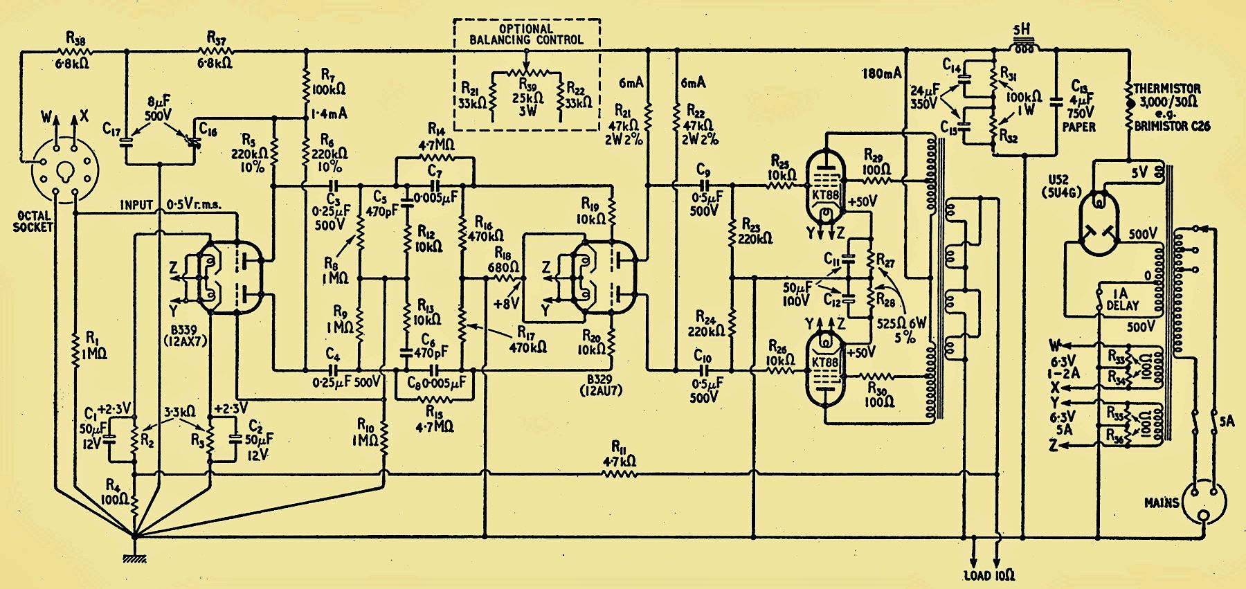
The unit could be something like this generic push-pull amp.

58900f48-4f6e-42ca-a2ed-8ba5e0893351.jpg
 
Only one 12ax7 per channel though, so it won't be that involved.

Could be a paraphase inverter, thats the first section of that amp schematic above. More precisely thats a floating paraphase, but mostly the difference is moving a couple resistors around.
Could be one triode for voltage gain and one as a split load.
Less likely but not impossible is a long tail pair, just with no voltage amp stage.

AC balance is usually just one pot though, no matter how the inverter is designed so maybe the second pot does something else?
 
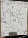
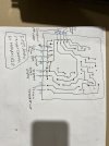
I know everyone is waiting for a schematic of the amp board! but i've never drawn one. So practiced with the power supply boards and the wiring for the whole unit. YES! the writing is bad
EDIT: note, The transformer wires are not marked correctly in/out. just marked that they are connected to it.
IMG_2075.jpegIMG_2077.jpegIMG_2078.jpegIMG_2079.jpegI got lazy on the last one and didnt mark components. but i dont think its nessecary..
 
Thanks for the drawings. Unfortunately, the circuit board tracings are not really needed to understand and fix an amp. You need to know the stages within an amp and how they are connected. This is prolly not directly related to how the circuit board was printed.

You can fix this unit without having the schematic, if you know the basics of this particular amp, what went wrong, why it went wrong, what to replace, and check.

If you haven't fixed an amp like this before or don't really understand how it works, you may not want to tackle it. Long-distance hints from a website may give you the answer that you need, or they can lead you down the wrong road. Which may be hard to recover from.

Just a little warning.

:thumbsup:
 
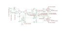
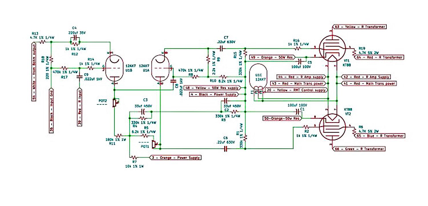
So I learned KiCad and made a schematic. its a bit messy. but first time. almost done replacing components. will power up with variac to get some voltages and polarity for the wire connections. have also had to replace some out of spec resistors. the 4.7Ks got pretty burned up.

This is only the right channel amp. The left is basically the same

Pdf is attached at bottom to make it easier to see. The png just gets blurry.

Thanks for everyone helps so far

Fezz2.0.jpg

Titania pdf
 
This looks like a split load inverter with resistor values that make no sense for a 12AX7. Might want to check R5 and R10. I could believe 82K, but I don't believe 8.2K. 5 stripe resistors regularly screw me up, and orange v red does too.

anyway, pot1 would act as an AC balance pot. Its trimming the total plate resistor value so the plate and cathode resistance matches for equal output, or maybe the transformers are imperfect and it wants a smidgen of imbalance to minimize distortion.

Pot2 doesn't make a lot of sense though. Its in the plate resistor circuit so its altering the plate resistance but I don't understand why. The voltage amp and phase inverter are cap coupled so the plate voltage at V1B doesn't affect the current through V1A at all. It would alter open loop gain but with negative feedback it would hardly be noticeable.
 
corrected R5,R10,R13:naughty:
yeh, the orange/red/brown are barely distinguishable. the kt88 pin 4 4.7ks its like heat has burned the pigment on the bands leaving only black lines
double checked pot circuits, that is how they connect


Fezz2.0.jpg
Titania PDF2
 
just as a point of convenience, maybe flip the whole thing top to bottom. If the 12ax7 plates were on the top and the cathodes on the bottom it would be a little easier to follow.


You can also just ignore the heater wiring, or draw it in off to the side rather than in the middle.

4.7K for a screen resistor seems way too big. I'd expect less than 1K there. Sure its not 470 ohm? I didn't notice that previously, wasn't really looking beyond what the pots do.
 
Update:
After replacing the caps, checking resistors, getting new matched tubes....
It didn't work! and blew a cap instantly.
I hadn't fully soldered one of the screen grid wires, which caused the voltages to go up and down erratically.
Fixed that.
And it is working great. No need to touch the pots.

Also,
Fezz got back in touch! email from a nice guy. Quoting
"It is older design indeed. You figured right - one pot is for AC balance (in fact completely unnecessary regulation, if one knows how split load phase inverter works) and one is for regulation of load in anode of voltage amplifier preceding phase splitter. I believe that the idea of designer was to enable small gain regulation, so you can balance the difference between tubes in two channels, which will occur as different gain level, due to extremely low NFB factor."

in other words, leave them alone!

Left it running for a few different days and time periods. No distortion or overheating.
Thanks for yalls help
 
The AC balance pot really isn't needed in the modern era of stable resistors. Thats actually the single coolest thing about a split load inverter. If the plate and cathode resistors are equal, the output will be equal in amplitude.

Makes a lot more sense with old carbon resistors that change value considerably though. It can be useful if you need slightly imperfect balance, sometimes transformers or output tubes are out of whack enough that tweaking the AC balance can reduce distortion. Lacking a THD analyzer if you just measure the cathode to ground resistance and make the plate to B+ resistance equal, it'll be plenty close enough.
 
Back
Top Bottom