• The move to the new server is done. There are some software and database maintenance updates in process. This has us passing the hat around to help out. We appreciate any donations. Seriously, even a dollar helps. The payment page may be found here - https://www.audiokarma.org/support.html

Filter cap buzz....should I worry?

z-adamson

Addicted Member
So, I have a Sansui z9000x.

One of the filter caps buzzes almost constantly as long as the receiver is turned on. I don't mean so loud it can be heard over the music that it is playing.

But with the volume down and my ear right next to it, the buzz is audible.

It seems to be performing fine for the moment.

The caps are new and have about 3 weeks of on and off use.

PS...I don't mean the buzz comes through the speakers. I mean the cap itself buzzes.
 
Register to hide this ad
excessive ripple or excessive current draw on that rail?
Does power up with DBT look ok?
 
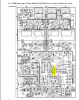
Wondering if a worthwhile test would be to disconnect the unregulated supply at pins 92,93,94 as per below.
This looks like a connector that can be unplugged. Certainly do not unsolder wire wrap or any wires. Then check
for buzz. Assume no oscilloscope to look at the ripple voltage on that cap?

upload_2019-9-9_9-33-56.png
 
excessive ripple or excessive current draw on that rail?
Does power up with DBT look ok?
I powered up with dbt before doing anything, good there. I monitored it for quite a while on the dbt. Also monitored bias and offset for a long time, to spec and stable.
 
Wondering if a worthwhile test would be to disconnect the unregulated supply at pins 92,93,94 as per below.
This looks like a connector that can be unplugged. Certainly do not unsolder wire wrap or any wires. Then check
for buzz. Assume no oscilloscope to look at the ripple voltage on that cap?

View attachment 1613173
I do have an oscilloscope, all I have done with it so far is analyze sine and square waves at dummy loads hooked to the amps outputs. Good there.
 
Wondering if a worthwhile test would be to disconnect the unregulated supply at pins 92,93,94 as per below.
This looks like a connector that can be unplugged. Certainly do not unsolder wire wrap or any wires.

Just confirmed that 92, 93, 94 are not unpluggable. They are wrapped wires.
 
Just confirmed that 92, 93, 94 are not unpluggable. They are wrapped wires.
Don't attempt to unwrap.

If I unplug that and buzz goes away, then what?
The idea was to remove part of the load. This was an error on my part

I do have an oscilloscope
Are you able to probe the filter cap terminals?
There are 2 filters, the positive of one and the negative of the other will be connected, normally a bar or solid wire, probably
with a few Black/ground wire connected at that point. The other cap terminals connect to the positive and negative power
rails, it's these terminals that you should probe,

Connect probe GND connection to amp chassis. Set oscilloscope to AC.
Probe cap terminal and take pic/measure peak to peak voltage, maybe 100-500mV?
Repeat for other cap terminal, expect about the same. Don't want to see 70mV on one and 3.2V on the other.
 
@mbz

Yes I am able to probe the filter cap terminals.

Double checking to make sure I follow....

Oscilloscope set to ac volts. Negative probe to chassis ground, positive probe to filter cap positive at each filter cap? Or am I probing filter cap pos on one and neg on the other because I am probing the cap terminals that do not bridge one cap to the other? I didnt quite follow you there.

Then what? Amp powered on and idling? Sine wave generator at 1000hz and dummy loads hooked up, low volume?

Basically I am looking to see if the waveform I get on one matches the other, of if there is a big difference. Right?
 
Last edited:
  • Like
Reactions: mbz
pos on one and neg on the other because I am probing the cap terminals that do not bridge one cap to the other?
Yep, that's it, probe the non-bridged pos on one cap then repeat for the other cap.

Then what? Amp powered on and idling? Sine wave generator at 1000hz and dummy loads hooked up, low volume?
Good point. Do whatever (load/input/volume) to get the cap to buzz, first try no input etc...
Do the measurement when cap buzzes
 
Yep, that's it, probe the non-bridged pos on one cap then repeat for the other cap

Non-bridged pos on one cap and non-bridged neg for the other, right? Since pos and neg are bridged that leaves a pos and a neg to probe.

So, black probe to chassis and red probe to unbrigded NEG on one filter cap.

Black probe to chassis and red probe to unbridged POS on the other filter cap.

Right? Just double checking.
 
Right? Just double checking.
yep, you got it, correct on all points.

Odd that your oscilloscope has red and black probes. Normally one of the probes has a wire with an aligator clip
or similiar attached. It is this clip/wire that should be connected to chassis.
 
The cap may have loose foil windings. What you are hearing is probably an upper harmonic of the 120Hz. power supply ripple.
It may not cause any trouble but you can replace it if it bothers you. Talk to the parts vendor about it, you may get a free replacement.
 
Definitely replace that cap. Something is either arcing or vibrating inside of it, and it will probably short eventually.

Double check it's mounted securely, that might cause it.
 
So if I do mbz's test and it checks out, then I have verified that the circuitry outside of the filter cap is good, which means the problem is isolated to the filter cap itself.

Right?
 
All I'm saying is that excessive ripple at the filter cap might cause it to "rattle". The excessive ripple might
be caused by part failure of rectifier or maybe an increased current draw from the amp. Takes less than 5min
to power up the oscilloscope to capture waveform then we can dismiss this theory and move on.
 
All I'm saying is that excessive ripple at the filter cap might cause it to "rattle". The excessive ripple might
be caused by part failure of rectifier or maybe an increased current draw from the amp. Takes less than 5min
to power up the oscilloscope to capture waveform then we can dismiss this theory and move on.
Understood and I fully agree.

If it passes the ripple test, the circuitry outside of the filter caps is ruled out as a culprit, right? At that point, filter cap replacement is the next step, right?
 
Back
Top Bottom